MAN#650780
For HDX and RTX systems follow these steps:
•
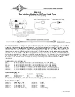
Make sure the BIM units are all connected to the gauge control box.
•
HDX: With the ignition on, press and hold both switches to enter SETUP. With external switches hold either
one while turning the ignition on. Release the switches when SETUP is shown.
•
RTX: With the ignition off, press hold the toggle switch in either direction, and then turn the ignition on to enter
SETUP. Release the switch when SETUP is shown.
•
Press and release either switch until BIM is selected. Press and hold either switch to enter BIM setup menu.
•
Release the
switch. A list of the BIM’s found should be shown. If NONE FOUND is displayed then check
connections to the BIM-12.
•
Press and release either switch until BIM-12 is selected.
•
Press and hold either switch to enter setup for this module.
•
Release the switch. The menu will show FORMAT, LABEL, WARN LO, WARN HI, CALIBRATE, BACK. Any
menu that does not apply to this BIM will be grey and cannot be selected.
•
Use either switch to select the option you wish to change. When you are finished select BACK to return to the
BIM selection menu.
•
When you are finished, select BACK to return to the BIM list menu, select BACK to return to the main menu,
and then select EXIT SETUP to return to normal operation.
With HDX/RTX systems the setup can also be done with the Dakota Digital app for Apple and Android devices.
Troubleshooting quick tips:
While the BIM is operating, the dot in the upper left corner of the display will indicate the status. On steady indicates it
is powered up but not receiving any bus activity. Flashing indicates it is communicating on the bus.
To see the sensor and channel status on the BIM display, press and hold the switch. The display will cycle through
three screens. The first will show the sensor input status. Each digit on the display will show the status for one of the
channels. ‘
’ indicates there is a bus ID conflict on that channel ID. ‘
−
’ indicates the sender is connected properly. ‘
’
indicates the sender is not connected or the signal is too high. ‘
’ indicates an internal measurement problem. If the
input is turned off the digit will be blank.
The second screen will show the ID assigned to channel 1. The third screen will show the ID assigned to channel 2.
Troubleshooting guide.
Problem
Possible cause
Solution
_
Sensor does not show on
PWR terminal does not have power.
Connect to a location that has power.
gauge readout.
GND terminal does not have a good
Connect to a different ground location.
BIM will not light up at all.
ground.
Module is damaged.
Return for service. (see instructions)
_
Sensor does not show on
Interface cable is not connected.
Connect the supplied power/data harness between the module and
gauge readout.
the gauge control box.
BIM has a steady dot lit
Interface cable is loose.
Make sure both ends of the cable are seated in securely.
On VHX systems, the BIM display
Follow instructions in VHX manual to enable the BIM display screen.
for this channel is disabled.
Another BIM is set with the same
Test module works when co
nnected to control box alone. Change ID’s
channel IDs.
on one of the modules so each module uses unique IDs.
_
Gauge lights up, but does
Loose connection on sensor wires.
Inspect and reconnect wires.
not read correctly.
Probe is mounted incorrectly.
Check probe mounting location.
Sensor wires are reversed.
Check that red is to RED and yellow is to YEL.
Voltage or wiring problem in the
Check wiring harness for loose or damaged wires.
vehicle wiring harness.
Gauge lights up, but displays Internal temperature measurement
Return for service. (see instructions)
“---”. (‘
’ on BIM)
problem.
Gauge lights up, but displays Sender is not connected to gauge.
Connect SND terminal on gauge to sender terminal.
“EEE”. (‘
’ on BIM)
Wire between gauge and sender is
Test and replace wire.
broken.
Sender is damaged.
Replace sender.
Module is damaged.
Return module for service. (see instructions)
BIM display shows
”
”
Data cable is damaged.
Inspect and replace power/data harness.
Another module on the bus is damaged Inspect other modules on the data bus.
or connected improperly.


