Dake 972001 Use And Maintenance Manual Download Page 13

Force 10M /Force 20M13

                                            13 

06/10 

Section 4.0


4.0 HANDLING, TRANSPORT AND POSITIONING 


For handling the packed machine, as described above 

(see section 3.0), it is necessary to use special lifting 

equipment whose maximum lifting capacity must be no 

lower than the total weight of the press. 


THE TOTAL WEIGHT OF THE PRESS PLUS PACKING 

IS SHOWN ON THE ADHESIVE TABS PLACED ON 

THE PACKING AND ON THE ACCOMPANYING 

DOCUMENTS. 


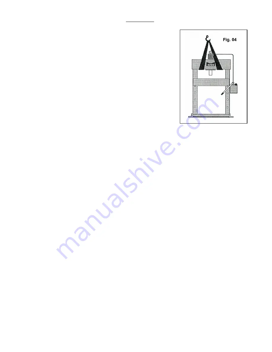
For loading and unloading the machine, lifting straps are 

to be used positioned as shown in Fig. 04. 


4.1 NOTICES FOR HANDLING AND TRANSPORT 


Loading and unloading will have to be done with lifting straps in conformity with and 

according to the instructions of the above paragraph, 

in addition check: 


  Check  that  the  straps  are  made  in  conformity  with  safety  regulations  and  they 

have attached the relative plates certifying they are in conformity with the standards. 


  CHECK  THAT  THE  MAXIMUM  CAPACITY  OF  EACH  STRAP  IS  GREATER 

THAN THE TOTAL WEIGHT OF THE PRESS. 


 Check that the straps are in a good state of repair. 


  It  is  forbidden  for  things  and/or  persons  to  stand  close  to  the  machine,  the 

unloading  or  loading  area,  and  the  means  of  transport  during  the  loading  and 

unloading phases. 


  Do  not  make  any  sudden  movements  with  the  lifting  equipment  while  lifting  or 

lowering the load. 


 Pay the utmost attention during all handling operations so that the press and in 

particular the hydraulic power unit does not get damaged. 


 Observe the in-house provisions concerning lifting and handling. 


 IT IS FORBIDDEN TO APPROACH OR PASS UNDER HANGING LOADS. 


THE MANUFACTURER DECLINES ALL LIABILITY FOR ANY DAMAGE CAUSED 

BY  ANY  ACTION  DURING  THE  PHASE  OF  UNLOADING  AND  LOADING  THE 

PRESS. 


Summary of Contents for 972001

Page 1: ...e Manual Hydraulic Press Manual Pump Model No _________________ Serial No _________________ 724 Robbins Road Grand Haven Michigan 49417 616 842 7110 Phone 800 937 3253 616 842 0859 Fax 800 846 3253 Web www dakecorp com E mail customerservice dakecorp com technicalsupport dakecorp com ...

Page 2: ...dical and punctual written notes on what has been carried out in the maintenance phase indicates meticulousness but above all it becomes a clear diary of what has been done and what will have to be done at the next maintenance deadline 5 For further information please do not hesitate to call our Dake Technical Service department at 1 800 846 3253 remembering to give the model name and serial numbe...

Page 3: ...rk Examples rigid helmet safety shoes safety earmuffs close fitting overalls industrial gloves etc Keep cuffs buttoned Do not wear a tie or scarf or long hair ATTENTION tools Always check that your tools are in good condition and that the tools are suitable for the work to make ex don t use the pliers as hammers etc ATTENTION repairs Don t make repairs or any other service that you are not familia...

Page 4: ...aulic oil neither put your face close to them but use a piece of cardboard to check for any leaks on them If hydraulic oil penetrates into your skin get treatment from a doctor immediately CAUTION o rings and gaskets Gaskets and o rings fitted incorrectly damaged or worn may cause leaks and accidents Do not use thinners solvents or acids close to o rings and gaskets CAUTION operator For no reason ...

Page 5: ... parts section SECTION 3 0 UNPACKING 3 1 Disposing of the packing SECTION 4 0 HANDLING TRANSPORTING AND POSITIONING 4 1 Notices for handling and transporting 4 2 Positioning the press SECTION 5 0 COMMISSIONING AND START UP 5 1 Filling the press with oil 5 2 Starting the machine 5 3 Discharging the air 5 4 Maximum pressure adjustment SECTION 6 0 SAFETY INSTRUCTIONS SECTION 7 0 OPERATION 7 1 Control...

Page 6: ... its monolithic structure has considerable bending strength 2 The HAND PUMP placed on the right of the press allows with facility to reach the work pressure 3 The HYDRAULIC CYLINDER specially designed for the specific requirements of use of the press In addition to the special care for the internal surfaces and of the rod special low friction gaskets have been used in it to optimize the operations...

Page 7: ...e their location The operator will have to check that these labels are present on the machine and fixed in a stable manner In the event of any of them missing or having deteriorated it will be necessary to immediately notify the person in charge of safety and to forward a request to the manufacturer WARNING LABELS To the left is the safety Alert symbol When you see these safety alert symbols on yo...

Page 8: ...Force 10M Force 20M8 8 06 10 Label 300168 Label 84487 Label 84399 Label Placement View 300168 84487 84399 81002 607 Label 607 ...

Page 9: ...ition that is in front of the hydraulic power unit It is forbidden to use equipment or carry out operations that may have even the slightest chance of projecting splinters or parts of equipment Section 2 0 2 0 TECHNICAL DATA SHEET Below we give a table summarizing the technical dimensional particulars of the DURA series Presses Model Dura Press Ton Max Width between Uprights Width between Table Ch...

Page 10: ...rt Number Item No Description Force 10M Force 20M 1 Gauge Bar 300357 300358 Gauge in tons 301723 301722 2 Hand Pump Complete 300366 301485 3 Hydraulic Cylinder Complete 300652 301343 4 Piston Gasket 300796 301558 5 Spring 300797 301560 6 Head Scraper 300798 301561 Fitting for gauge 301888 301888 1 2 3 4 5 6 ...

Page 11: ...302368 302368 20 29 Valve 302369 302369 31 32 33 Valve 302370 302370 30 Filter N A N A 34 Rod assembly 302373 302373 6 Spring 302372 302346 5 Cap 302371 302371 25 Tap Screw N A N A Complete Pump 300366 301485 Gasket Repair Kit 301327 301542 Linkage Assembly Item 9 10 11 15 16 34 301575 301574 Relief Valve Item 1 2 3 4 5 301576 Relief Valve 4NV 301573 If n a is shown must replace entire pump ...

Page 12: ...cumentation After removing the plastic unbolt the lag bolts from the skid For handling and transport please refer to Section 4 0 3 1 DISPOSING OF THE PACKING The packing will have to be disposed of by the purchaser in compliance with their local regulations The elements comprising the packing e g plastic bags polystyrene nails nylon etc MUST NOT be left within the reach of children as they are a s...

Page 13: ...made in conformity with safety regulations and they have attached the relative plates certifying they are in conformity with the standards CHECK THAT THE MAXIMUM CAPACITY OF EACH STRAP IS GREATER THAN THE TOTAL WEIGHT OF THE PRESS Check that the straps are in a good state of repair It is forbidden for things and or persons to stand close to the machine the unloading or loading area and the means o...

Page 14: ... earth sand etc PAY THE UTMOST ATTENTION TO OVERHEAD ELECTRICITY LINES Check beforehand the position of any overhead electricity lines and mark them with special warning cards Always consider a suitable distance from the sliding paths for the means of transport elevators transpallets etc sudden and unexpected sources of danger Check that the position identified is always served by adequate lifting...

Page 15: ...shipped without oil After you have filled up the tank you have to stroke the hand pump until the ram is fully extended out of the cylinder release the wheel under the pump to return the ram You have to verify the oil level in the tank and if needed refill the tank You have to repeat the above mentioned operation sometimes to bleed the air from the system See Air Discharge Section 5 3 The level of ...

Page 16: ...der and wrap it in a cloth to avoid oil splashes Stroke the hand pump to remove the air Verify that all the air has been bled out of the system when only oil is expelled from the fitting Tighten the nipple This operation must be continued until oil is completely free of air bubbles or froth After discharging the air it is necessary to top off the oil level in the unit 5 4 MAXIMUM PRESSURE ADJUSTME...

Page 17: ...gle operator Use of the press is reserved exclusively for authorized and qualified personnel informed about the risks deriving from its use Before operating the machine the operator will check that there is no equipment or persons in the immediate vicinity of the machine whose presence may be dangerous for themselves and for others All work requiring the piece to be pressed to be supported by the ...

Page 18: ...placed under the pump control lever The cylinder is equipped with a spring for the ram return 7 2 HEIGHT ADJUSTMENT OF THE MOVABLE BASE To get very good use of the press it is necessary to place the worktable at a correct height depending on the operation to make and on the tooling to use 1 To the size of the part to be pressed 2 To any tooling placed on the movable table 3 With the help of a seco...

Page 19: ... hole on the top of the oil tank Visual inspection of the oil level should be approximately below the top of the tank Any topping off has to be done with the same type of and clean oil used in the filling phase of the system and with the same procedures as regards cleaning the fluid It is advised to note the type of oil used on a card affixed onto the unit or on the last few pages of this manual c...

Page 20: ...uides Do not use solvents or aggressive acids Section 9 0 9 0 MALFUNCTIONING CAUSES and REMEDIES 9 1 CYLINDER MALFUNCTIONING Call Dake Technical Service 1 800 937 3253 CYLINDERS MALFUNCTION ORIGIN REMEDY The cylinder moves irregularly Air in the pump Air in the circuit Damage cylinder gaskets Damage or worm pump Sequence valve jammed Delivery pipe clogged or choked Bleed the air Bleed the air Repl...

Page 21: ...ND DIVISION OF MATERIALS If you are not going to use the appliance any more it is recommended to make it inoperative by removing the oil contained in the tank and eliminating the oil remaining in the cylinder pipes pump body and valves When going for demolition the press must be treated as special waste it must therefore be split up into its homogeneous parts these parts must be separately dispose...

Page 22: ...82 PSI 4 Ton 121 bar 1825 PSI 3 Ton 90 bar 1369 PSI 2 Ton 60 bar 913 PSI 1 Ton 30 bar 456 PSI Gauge Conversion 20 ton Bore 80 mm 3 149 20 Ton 340 bar 5136 PSI 15 Ton 255 bar 3852 PSI 10 Ton 170 bar 2568 PSI 5 Ton 85 bar 1284 PSI 4 Ton 68 bar 1027 PSI 3 Ton 51 bar 770 PSI 2 Ton 34 bar 514 PSI 1 Ton 17 bar 257 PSI ...

Reviews: