background image

Si50-203

Overhaul

Semi-Hermetic Single Screw Compressor Version III

3

2.

Overhaul

Generally, maintenance and inspection of equipment are important in preventing their failure 
and damage to them.  Equipment, even without defective structure or components, gradually 
age and wear over long years of operation.  For example, screw compressors, despite their 
apparent good operating condition, may face such problems as decreasing insulation resistance 
of the motor, oil deterioration, and worn and fatigued bearings during long periods of operation.  
Most of such changes with time are invisible from the outside in many cases, and it is only after 
an accident that they are noticed.  For this reason, in the case of equipment required to be 
highly reliable, it is most important to grasp their wear condition precisely and take necessary 
measures against accidents if they are to maintain proper operating conditions for expanding 
service life.

Overhaul interval:  40,000 hours or 7 years, whichever comes first.

Summary of Contents for ZH(C)3LSF

Page 1: ...The specifications designs and information in this manual are subject to change without notice Printed in Japan 02 2003 AK Semi Hermetic Single Screw Compressor Version For Overhaul and Inspection Ap...

Page 2: ...Inspection Instructions 5 4 Overhaul Instructions 10 4 1 Disassembly and Inspection 11 4 2 Replacing The Bearing 20 4 3 Final Assembly 24 5 Airtightness Test 29 6 Charging Oil 30 7 Caution in Test Ope...

Page 3: ...i hermetic single screw compressor for use in Model F type ZH_F G type ZH_G Replacement intervals specified in the booklet are empirically worked out based on the design service life expected of the c...

Page 4: ...problems as decreasing insulation resistance of the motor oil deterioration and worn and fatigued bearings during long periods of operation Most of such changes with time are invisible from the outsid...

Page 5: ...dic Inspection Items and Intervals Table 3 1 shows periodic inspection items and intervals Conduct inspections at the earliest indicated inspection intervals Table 3 1 Periodic inspection items and in...

Page 6: ...ime because absorption current flows through the insulated object at an early stage lowering the resistance value correspondingly 2 Prohibit anyone from measuring insulation resistance in a vacuum It...

Page 7: ...th check valve of the compressor see Fig 3 2 Remove the partition lid then tighten the flare nut to discharge refrigerant from the compressor To loosen and tighten the flare nut use two wrenches to tu...

Page 8: ...e visible on the level gauge during equipment operation Take care not to let in air or dust and other foreign particles remaining on the bottom of the oil container When charging oil from a previously...

Page 9: ...and it affects the compressor performance and reliability to a great extent Therefore the slit clearance must be set properly 60 to 90 m While pressing the periphery of the gate rotor shaft with finge...

Page 10: ...lid then tighten the flare nut to discharge refrigerant from the compressor Same as Section 3 2 2 3 Disconnect the suction pipe and remove the suction filter 4 Remove dust and foreign particles from t...

Page 11: ...rew Compressor Version III 4 Overhaul Instructions The driving and friction parts in the compressor wear for prolonged over time To prevent accidents caused by worn parts it is necessary to inspect th...

Page 12: ...de and The Discharge End Cover in case of ZH9F oil collector Receive remaining oil with a drain pan Be sure to mount guide bolts when removing the discharge end cover Be careful not to damage the oil...

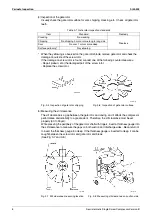
Page 13: ...e exceed the standard value replace the gate rotor Standard value 0 15 mm or less for all teeth ZH3 5 and 0 20mm or less for all teeth ZH7 9 Fig 4 4 Measurement of gate rotor backlash 4 Disassembling...

Page 14: ...units In the guide bolt hole thread the bolt that was used for the lower bearing holder mounting and lift the lower bearing holder from the casing Remove the shims inserted between the lower bearing...

Page 15: ...replace it with a new one 4 Install the gate rotor on the shaft and mount the C type retaining ring The gate rotor has front and back sides Position the gate rotor so that the manufacturing number is...

Page 16: ...rewdriver 2 Loosen the lock nut Use the special tool or jig 1 3 As shown in Fig 4 11 grip rotor fins with pliers and remove the rotor Securely support the rotor so as not to drop the rotor At removal...

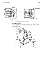
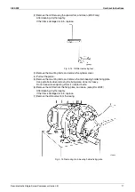
Page 17: ...Fig 4 12 Cross sectional diagram of controller 1 Remove the slide valve arm Loosen the two locking nuts of the slide valve shaft and the bolt at the center of the arm A thread lock compound was used...

Page 18: ...ts and remove the cylinder cover 4 Pull out the piston 5 Remove the mounting bolts and remove the main bearing holder fixing plate Use guide bolts when removing the fixing plate since it is heavy Do n...

Page 19: ...r 2 Removing the screw shaft Push the screw shaft from the suction side until the bearing holder completely extends from the discharge side Then pull out the shaft from the discharge side Insert one h...

Page 20: ...sion III 19 Fig 4 18 Removing screw shaft 2 3 Disassembling the screw assembly Remove the bolts and remove the screw bearing retainer plate Remove the main bearing holder from the screw shaft Do not l...

Page 21: ...al jig 2 to remove the outer ring 2 Screw shaft inner ring of cylindrical roller bearing Remove the C type retaining ring Remove the inner ring of the bearing by using a chisel Be careful not to scrat...

Page 22: ...y placing a bronze rod and hammering it Since the outer ring is not pressed in deeply it can be removed easily Fig 4 22 Removing main bearing holder bearing 2 Gate Rotor Bearings Angular Contact Beari...

Page 23: ...the housing mount the C type retainer ring to secure the bearing 2 Screw shaft inner ring of cylindrical roller bearing Heat the inner ring of the bearing 120 C max and insert the tip of the screw sh...

Page 24: ...in the lower bearing holders mounted with the bearings and check the preload of the bearings Insert the gate rotor shaft into the bearings Install gate rotor shims 2 and the gate rotor bearing retaine...

Page 25: ...e Screw Shaft and Main Bearing Holder Install screw adjusting shims 2 and the main bearing holder on the screw shaft and install the screw bearing retainer plate Tighten the two bearing retainer plate...

Page 26: ...es The screw shaft is heavy and the main bearing holder rotates making it difficult to hold it Be careful not to drop the screw shaft during installation Fig 4 28 Inserting screw shaft 3 Installing Th...

Page 27: ...e holding section of the cylindrical roller bearing is made of plastic It can break easily if applied with impact Lift the screw shaft slightly higher than the side cap and gently insert the screw sha...

Page 28: ...ing bolts may damage the threads since they are too short for this process Before the casing and the flange of the lower bearing holder contact insert shims and tighten securely 4 Install the gate rot...

Page 29: ...ighten the four bolts around the cylinder After tightening bolts make sure the piston moves smoothly Fig 4 32 Adjusting piston and installing cylinder cover 6 Tighten the other mounting bolts of the c...

Page 30: ...or soap water to check for leaks Apply soap water on the side caps and other cover mounting sections to make sure no air bubbles are formed If air bubbles are formed release the pressure then re tigh...

Page 31: ...Part of oil may remain in the refrigerating system Therefore charge the same amount of oil removed from the compressor during disassembly When a new gate rotor is installed pour about a half of the to...

Page 32: ...ake sure all bolts are tightened 2 Check the wiring for proper connection 3 Conduct inching Check the rotating direction using high and low pressure gauges If the rotating direction is correct the low...

Page 33: ...Fixing plate and cover installation 5 Other general tools Adjustable end wrench spanners pliers screwdrivers hammer plastic hammer T shape wrenches chisel Measuring instruments 6 Megger taster 500 V...

Page 34: ...ng Jig Applicable model ZH3_ ZH5F ZH7F ZH9F ZH5G ZH7G ZH9G 150 200 250 150 200 7 0 7 6 8 1 7 0 8 1 5 6 7 6 7 76 3 89 1 101 6 76 3 101 6 66 75 92 70 86 10 10 12 10 11 Material STPG370E 65A sch80 STPG37...

Page 35: ...late 1 SS400 or SM400A See next page Batten 1 2 SS400 or SM400A See next page Batten 2 1 SS400 or SM400A See next page Removing bolt 1 S45C JIS B1180 fully threaded hexagon head bolt A M10x70 10 9 cha...

Page 36: ...Si50 203 Required Tools Semi Hermetic Single Screw Compressor Version III 35 Jig 2 1 Bearing Removing Jig Parts...

Page 37: ...tity Material Remarks Guide plate 1 SS400 or SM400A See next page Batten 1 SS400 or SM400A See next page Removing bolt 1 S45C See next page Hexagon bolt 2 S45C JIS B1180 hexagon head bolt with nominal...

Page 38: ...12 8 12 9 13 9 13 54 62 46 67 30 40 30 50 Removing bolt JIS B 1180 fully threaded hexagon head bolt A M8x70 10 9 chamfered end JIS B 1180 fully threaded hexagon head bolt A M12x70 10 9 chamfered end J...

Page 39: ...Required Tools Si50 203 38 Semi Hermetic Single Screw Compressor Version III Jig 3 Temporary Bearing Holder Mounting Plate jig For ZH3_ Material SS400...

Page 40: ...Si50 203 Required Tools Semi Hermetic Single Screw Compressor Version III 39 Jig 3 Temporary Bearing Holder Mounting Plate jig For ZH5_ Material SS400...

Page 41: ...Required Tools Si50 203 40 Semi Hermetic Single Screw Compressor Version III Jig 3 Temporary Bearing Holder Mounting Plate jig For ZH7_ Material SS400...

Page 42: ...Si50 203 Required Tools Semi Hermetic Single Screw Compressor Version III 41 Jig 3 Temporary Bearing Holder Mounting Plate jig For ZH9_ Material SS400...

Page 43: ...andle Jig Set Parts No Name Handle Stay 1 Stay 2 Disc Straight pin Material STPG370E SS400 or SM400A SS400 or SM400A SS400 or SM400A S45C Remarks 20A sch40 t2 9 JIS B1354 Class A or equivalent ZH3_F 3...

Page 44: ...Z0125 Parts No Name Handle Stay 1 Stay 2 Disc Straight pin Material STPG370E SS400 or SM400A SS400 or SM400A SS400 or SM400A S45C Remarks 20A sch40 t2 9 Refer next page JIS B1354 Class A or equivalent...

Page 45: ...Jig 4 2 Handle Jig Parts Z0126 Applicable model ZH3_F ZH3_G ZH5_ ZH7_ ZH9_ 6 6 8 8 8 6 6 8 8 8 20 20 24 24 24 22 26 28 32 36 50 5 50 5 60 5 75 5 80 5 7 7 8 11 11 60 60 70 85 90 0 012 0 0 012 0 0 015 0...

Page 46: ...i Hermetic Single Screw Compressor Version III 45 Jig 5 Oil Filter Removing Jig For ZH3_F Parts No Name Handle Stay 1 Stay 2 Spanner Material STPG370E SS400 or SM400A SS400 or SM400A SS400 or SM400A R...

Page 47: ...older Fixing Plate Assembling The Controller and Installing The Oil Filter 28 Installing The Motor Rotor 25 Installing The Suction End Cover 26 Insulation Resistance of The Motor 5 Insulation Resistan...

Page 48: ...Si50 203 ii Index...

Page 49: ...ting Plate jig For ZH7_ Material SS400 40 Jig 3 Temporary Bearing Holder Mounting Plate jig For ZH9_ Material SS400 41 Jig 4 1 Handle Jig Set 42 Jig 4 2 Handle Jig Parts 44 Jig 4 2 Handle Jig Set 43 J...

Page 50: ...Si50 203 iv Drawings Flow Charts...

Page 51: ...The specifications designs and information in this manual are subject to change without notice Printed in Japan 02 2003 AK Semi Hermetic Single Screw Compressor Version For Overhaul and Inspection Ap...

Reviews: