Maintenance
www.DaikinApplied.com 71
IOM 1281-2 • CENTRIFUGAL WATER CHILLERS
Maintenance Schedule Notes
1) Some compressors use power factory correction capacitors
and all have a surge capacitor (excepting units with solid state
starters). The surge capacitor can be installed out of sight in
the compressor motor terminal box. In all cases, capacitors
must be disconnected from the circuit to obtain a useful
Megger reading. Failure to do so will produce a low reading. In
handling electrical components, only fully qualified technicians
must attempt service
2) Approach temperature (the difference between the leaving
water temperature and the saturated refrigerant temperature)
of either the condenser or evaporator is a good indication of
tube fouling, particularly in the condenser, where constant
flow usually prevails. Daikin Applied’s high efficiency heat
exchangers have very low design approach temperatures, in
the order of one to one and one half degrees F.
The chiller unit controller can display the water and the
saturated refrigerant temperatures. Simple subtraction will give
the approach. It is recommended that benchmark readings
(including condenser pressure drop to confirm future flow
rates) be taken during startup and then periodically afterward.
An approach increase of two-degrees or more would indicate
that excessive tube fouling could be present. Higher than
normal discharge pressure and motor current are also good
indicators
3) Evaporators in closed fluid circuits with treated water or
anti-freeze are not normally subject to fouling, however it is
prudent to check the approach periodically. Some evaporators
may have a mixture of ¾-inch and 1-inch tubes.
4) Performed when contracted for, not part of standard initial
warranty service.
5) Oil filter change and compressor teardown and inspection
should be done based on the results of the annual oil test
performed by a company specializing in this type of test.
Consult Daikin Applied service for recommendations.
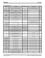
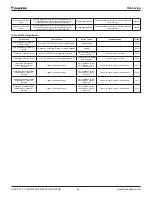
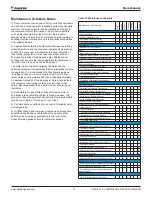
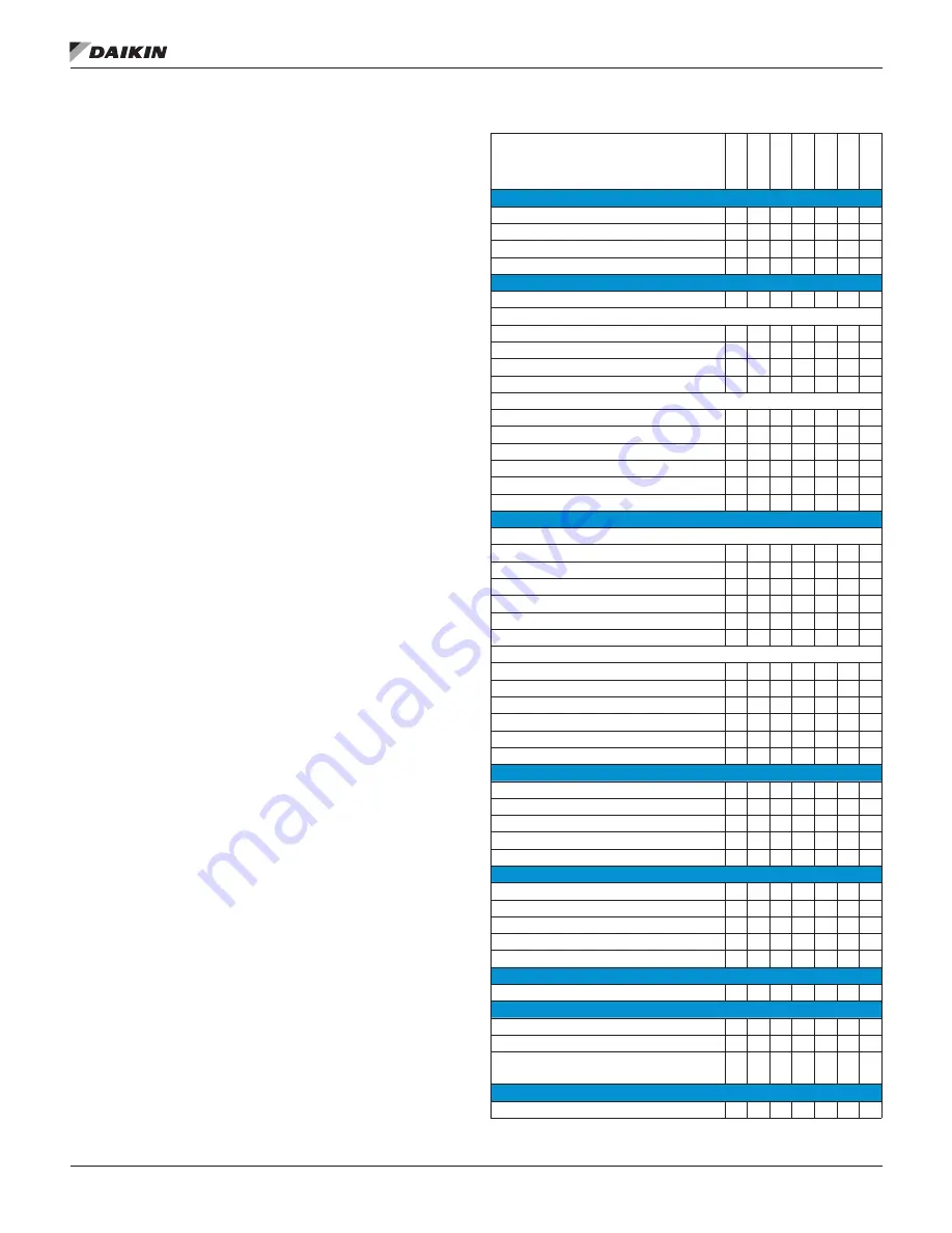
Table 31: Maintenance Schedule
Maintenance Check List Item
Daily
W
eekly
Monthly
Quarterly
Annually
5-Yr
As Req’d
Unit
Operational Log
O
Analyze Operational Log
O
Refrigerant Leak Test Chiller
O
Test Relief Valves or Replace
X
Compressor
Vibration Test Compressor
X
Motor
Meg. Windings (Note 1)
X
Ampere Balance (within 10% at RLA)
O
Terminal Check - measure infrared temp
X
Motor Cooling Filter Drier Pressure Drop
X
Lubrication System
Clean Oil Cooler Strainer (water)
X
Oil Cooler Solenoid Operation
O
Oil Appearance (clear color, quantity)
O
Oil Filter Pressure Drop
O
Oil Analysis (Note 5)
X
Oil change if indicated by oil analysis
X
Controls
Operating Controls
Calibrate Temperature Transducers
X
Calibrate Pressure Transducers
X
Check Vane Control Setting & Operation
X
Verify Motor Load Limit Control
X
Verify Load Balance Operation
X
Check Oil Pump Contactor
X
Protective Controls - Test Operation of:
- Alarm Relay
X
- Pump Interlocks
X
- Guardistor and Surgeguard Operation
X
- High and Low Pressure Cutouts
X
- Oil Pump Pressure Differential Cutout
X
- Oil Pump Time Delay
X
Condenser
Evaluation of Temp Approach (NOTE 2)
O
Test Water Quality
V
Clean Condenser Tubes (NOTE 2)
X
X
Eddy current Test - Tube Wall Thickness
V
Seasonal Protection
X
Evaporator
Evaluation of Temp Approach (NOTE 2)
O
Test Water Quality
V
Clean Evaporator Tubes (NOTE 3)
X
Eddy current Test - Tube Wall thickness
V
X
Seasonal Protection
X
Expansion Valves
Operational Evaluation (Superheat Control)
X
Starter
Examine Contactors (hardware & operation)
X
Verify Overload Setting and Trip
X
Test Electrical Connections (Infrared temp
measurement)
X
Optional Controls
Hot Gas Bypass (verify operation)
X

