
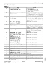

15 Electrical installation
Installation and operation manual
27
RK RKXYQ8T7Y1B
VRV IV compressor unit for indoor installation
4P499900-1A – 2020.10
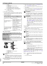
b
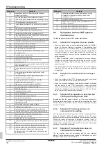
Contains fluorinated greenhouse gases
2
1
1
1
2
2
kg
tCO
2
eq
GWP × kg
1000
=
=
+
kg
=
kg
=
GWP: XXX
RXXX
a
f
c
d
e
a
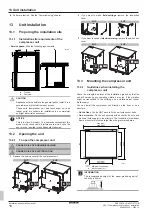
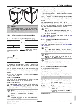
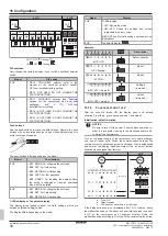
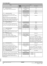
If a multilingual fluorinated greenhouse gases label is
delivered with the unit (see accessories), peel off the
applicable language and stick it on top of
a
.
b
Factory refrigerant charge: see unit name plate
c
Additional refrigerant amount charged
d
Total refrigerant charge
e
Quantity of fluorinated greenhouse gases
of the total
refrigerant charge expressed as tonnes CO
2
equivalent.
f
GWP = Global warming potential
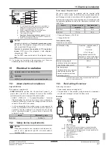
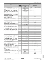
NOTICE
Applicable legislation on
fluorinated greenhouse gases
requires that the refrigerant charge of the unit is indicated
both in weight and CO
2
equivalent.
Formula to calculate the quantity in CO
2
equivalent
tonnes:
GWP value of the refrigerant × total refrigerant
charge [in kg] / 1000
Use the GWP value mentioned on the refrigerant charge
label.
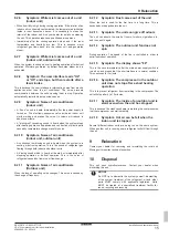
2
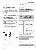
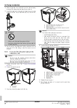
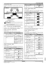
Fix the label on the inside of the compressor unit. There is a
dedicated place for it on the wiring diagram label.
15
Electrical installation
DANGER: RISK OF ELECTROCUTION
WARNING
ALWAYS use multicore cable for power supply cables.
15.1
About electrical compliance
Only for RKXYQ8
This equipment complies with:
▪
EN/IEC 61000‑3‑12
provided that the short-circuit power S
sc
is
greater than or equal to the minimum S
sc
value at the interface
point between the user's supply and the public system.
▪ EN/IEC
61000‑3‑12
=
European/International
Technical
Standard setting the limits for harmonic currents produced by
equipment connected to public low-voltage systems with input
current >16 A and ≤75 A per phase.
▪ It is the responsibility of the installer or user of the equipment to
ensure, by consultation with the distribution network operator if
necessary, that the equipment is connected only to a supply
with a short-circuit power S
sc
greater than or equal to the
minimum S
sc
value.
Model
Minimum S
sc
value
RKXYQ8
3329 kVA
15.2
Safety device requirements
NOTICE
When using residual current operated circuit breakers, be
sure to use a high-speed type 300 mA rated residual
operating current.
Power supply: Compressor unit
The power supply must be protected with the required safety
devices, i.e. a main switch, a slow blow fuse on each phase and an
earth leakage protector in accordance with the applicable legislation.
Selection and sizing of the wiring should be done in accordance with
the applicable legislation based on the information mentioned in the
table below.
Model
Minimum circuit
ampacity
Recommended
fuses
RKXYQ5
13.5 A
16 A
RKXYQ8
17.4 A
20 A
▪ Phase and frequency: 3N~ 50 Hz
▪ Voltage: 380-415 V
Transmission wiring
Transmission line section:
Transmission wiring
Sh shielded cable (2
wires)
Vinyl cords
0.75~1.25 mm²
(using shielded cable for the
transmission wiring is mandatory
for 5 HP, and optional for 8 HP)
Maximum wiring length
(= distance between compressor
unit and furthest indoor unit)
300 m
Total wiring length
(= distance between compressor
unit and all indoor units, and
between compressor unit and
heat exchanger unit)
600 m
If the total transmission wiring exceeds these limits, it may
result in communication error.
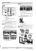
15.3
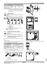
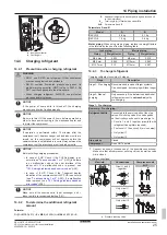
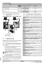
Field wiring: Overview
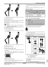
Field wiring consists of:
▪ Power supply (always including earth)
▪ Communication (= transmission) wiring between the compressor
unit, the heat exchanger unit, and the indoor units.
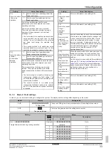
Example:
g
f
F1/F2
(16 V)
F1/F2
(16 V)
220-240 V
1~ 50 Hz
e
c
a
d
b
220-240 V
1~ 50 Hz
380-415 V
3N~ 50 Hz
a
Main switch
b
Earth connection
c
Power supply wiring (including earth) (sheathed cable)
F1/F2
Transmission wiring (sh shielded cable) (using
shielded cable for the transmission wiring is mandatory for
5 HP, and optional for 8 HP)
d
Compressor unit
e
Heat exchanger unit
f
Indoor unit
g
User interface


