Daikin VRV FXMQ100P7VEB9 Installation And Operation Manual Download Page 7


FXMQ50-125P7VEB9
VRV System air conditioners
3P468515-4 – 12.2016

Installation and operation manual

4

I

NDOOR


UNIT


INSTALLATION

When installing optional accessories (except for the air inlet panel),
read also the installation manual of the optional accessories.
Depending on the field conditions, it may be easier to install optional
accessories before the indoor unit is installed.

1

Install the indoor unit temporarily.

-

Attach the hanger bracket to the suspension bolt. Be sure to 
fix it securely by using a nut and washer from the upper and 
lower sides of the hanger bracket. 

(See figure 4)

2

Check if the unit is horizontally levelled.

-

Do not install the unit tilted. The indoor unit is equipped with a 
built-in drain pump and float switch. (If the unit is tilted against 
condensate flow, the float switch may malfunction and cause 
water to drip.)

-

Check if the unit is levelled at all four corners with a water 
level or a water-filled vinyl tube as shown in 

figure 9

.

3

Tighten the upper nut.

R

EFRIGERANT


PIPING


WORK

For refrigerant piping of outdoor unit, refer to the installation manual
supplied with the outdoor unit.

Before rigging tubes, check which type of refrigerant is used.

Use a pipe cutter and flare suitable for the used refrigerant.

To prevent dust, moisture or other foreign matter from infiltrating
the tube, either pinch the end, or cover it with tape.

Use copper alloy seamless pipes (ISO 1337).

The outdoor unit is charged with refrigerant.

To prevent water leakage, execute heat insulation work
completely on both sides of the gas and liquid piping. When
using a heat pump, the temperature of the gas piping can reach
up to approximately 120°C, use insulation which is sufficiently
heat resistant.

Be sure to use both a spanner and torque wrench together when
connecting or disconnecting pipes to/from the unit.

Do not mix anything other than the specified refrigerant, such as
air, etc..., inside the refrigerant circuit.

Use annealed material only for flare connections.

Refer to 

Table 1

 for the dimensions of flare nut spaces and the

appropriate tightening torque. (Overtightening may damage the
flare and cause leaks.)
Table 1 

When connecting the flare nut, coat the flare inner surface with
ether oil or ester oil and initially tighten 3 or 4 turns by hand
before tightening firmly.

If the refrigerant gas leaks during the work, ventilate the area. A
toxic gas is emitted by the refrigerant gas being exposed to a fire.

Make sure there is no refrigerant gas leak. A toxic gas may be
released by the refrigerant gas leaking indoor and being
exposed to flames from an area heater, cooking stove, etc.

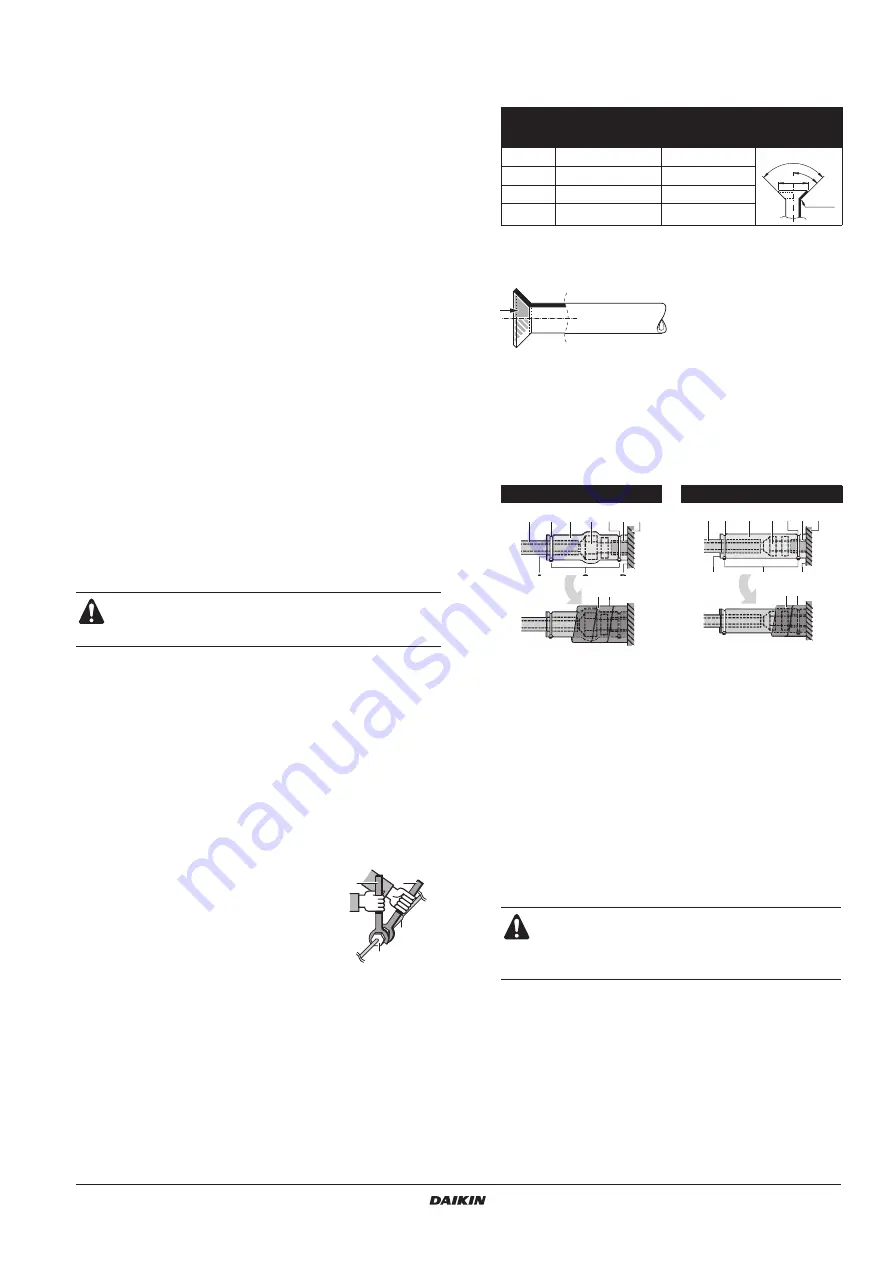
Finally, insulate as shown in the figures below.

Piping insulation procedure

1

Nut (field supply)

2

Washer for hanger bracket (supplied with the unit)

3

Tighten (double nut)

1

Water level

2

Vinyl tube

All field piping must be provided by a licensed refrigeration
technician and must comply with the relevant local and
national codes.

1

Torque wrench

2

Spanner

3

Piping union

4

Flare nut

1

2

4

3

Pipe 

gauge 

(mm)

Tightening torque 

(N•m)

Flare dimension 

A (mm)

Flare shape

Ø6.4

15~17

8.7~9.1

Ø9.5

33~39

12.8~13.2

Ø12.7

50~60

16.2~16.6

Ø15.9

63~75

19.3~19.7

Gas piping

Liquid piping

1

Piping insulation material (field supply)

2

Flare nut connection

3

Insulation for fitting (delivered with the unit)

4

Piping insulation material (main unit)

5

Main unit

6

Clamp (field supply)

7

Medium 1 sealing pad for gas piping (delivered with the unit)
Medium 2 sealing pad for liquid piping (delivered with the unit)

A

Turn seams up

B

Attach to base

C

Tighten the part other than the piping insulation material

D

Wrap over from the base of the unit to the top of the flare nut 
connection

For local insulation, be sure to insulate local piping all
the way into the pipe connections inside the unit.

Exposed piping may cause condensation or may
cause burns when touched.

R=0.4~0.8

45

° ±

2

90

°±

2

A

A

B

D

C

7

1

2

3

4

5

6

6

A

B

C

1

2

3

4

5

6

6

D

7

Summary of Contents for VRV FXMQ100P7VEB9

Page 1: ...INSTALLATION AND OPERATION MANUAL FXMQ50P7VEB9 FXMQ63P7VEB9 FXMQ80P7VEB9 FXMQ100P7VEB9 FXMQ125P7VEB9 System air conditioners ...

Page 2: ... 680 1 5 3 4 2 7 180 460 160 160 300 425 1 3 2 180 460 350 1 2 2 3 5 0 75 625 A 300 mm 1 1 5 m 2 3 1 4 100 mm 1 0 625 mm 1 1 2 4 5 3 6a 7a 7b 7c 6b 6c 8 9 10 11 2 1 3 5 4 700 630 A B 4 3 2 1 1 1 2 4 5 6 2 1 5 4 1 3 2 6 4 4 A A 1 2 3 4 5 6a 6b 6c 7a 7b 7c 8 9 10 11 ...

Page 3: ...tal como estabelecido em A e com o parecer positivo de B de acordo com o Certificado C 09 Примечание как указано в A и в соответствии с положительным решением B согласно Свидетельству C 10 Bemærk som anført i A og positivt vurderet af B i henhold til Certifikat C 11 Information enligt A och godkänts av B enligt Certifikatet C 12 Merk som det fremkommer i A og gjennom positiv bedømmelse av B ifølge Se...

Page 4: ...re machines generating electromagnetic waves exist Control system may malfunction Where the air contains high levels of salt such as air near the ocean and where voltage fluctuates a lot e g in factories Also in vehicles or vessels Do not install accessories on the casing directly Drilling holes in the casing may damage electrical wires and consequently cause fire This appliance is not intended for ...

Page 5: ...al appliances Noise may be generated depending on the conditions under which the electric wave is generated even if 1 meter is kept When installing the wireless remote controller kit the distance between wireless remote controller and indoor unit might be shorter if there are fluorescent lights who are electrically started in the room The indoor unit must be installed as far as possible away from fl...

Page 6: ...ng surface 2 Ceiling opening 3 Service access panel optional accessory 4 Air filter 5 Air inlet duct 6 Duct service opening 7 Interchangeable plate NOTE Before installation of the unit in case of installation with duct but no duct service opening modify the position of the air filters 1 Remove the air filter s at the outside of the unit 2 Remove the interchangeable plate 3 Install the air filter s fro...

Page 7: ...the specified refrigerant such as air etc inside the refrigerant circuit Use annealed material only for flare connections Refer to Table 1 for the dimensions of flare nut spaces and the appropriate tightening torque Overtightening may damage the flare and cause leaks Table 1 When connecting the flare nut coat the flare inner surface with ether oil or ester oil and initially tighten 3 or 4 turns by hand ...

Page 8: ... the drain raising pipes and insulate them 2 Connect the drain hose to the drain outlet on the indoor unit and tighten it with the clamp Precautions Install the drain raising pipes at a height of less than 625 mm Install the drain raising pipes at a right angle to the indoor unit and no more than 300 mm from the unit To prevent air bubbles install the drain hose level or slightly tilted up 75 mm T...

Page 9: ...legislation Note that the operation will restart automatically if the main power supply is turned off and then turned back on again This system consists of multiple indoor units Mark each indoor unit as unit A unit B and be sure the terminal block wiring to the outdoor unit and BS unit are properly matched If wiring and piping between the outdoor unit and an indoor unit are mismatched the system m...

Page 10: ...or units less than 12 A Branch the line outside the terminal board of the unit in accordance with electrical equipment standards when using two power wiring of a gauge greater than 2 mm2 Ø1 6 The branch must be sheathed in order to provide an equal or greater degree of insulation as power supply wiring itself 3 Do not connect wires of different gauge to the same grounding terminal Looseness in the...

Page 11: ... indications Ultra long life filter Light 10 000 hrs Heavy 5 000 hrs Long life filter 2 500 hrs 1 250 hrs Standard filter 200 hrs 100 hrs 2 Thermostat sensor selection Use both the unit sensor or remotesensorif installed AND the remote controller sensor See note 5 6 Use unit sensor only or remote sensor if installed See note 5 6 Use remote controller sensor only See note 5 6 3 Setting for display of ...

Page 12: ...on the outdoor unit If any other error display occurs on the display of the remote controller refer to Test operation on page 10 and the operation manual of the outdoor unit Check the defective point Using the remote controller Check on an indoor unit if the second code of mode No 21 is set to 01 factory setting Change the second code according to the external static pressure of the duct to be con...

Page 13: ...r is extremely contaminated If the dirt becomes impossible to clean change the air filter Air filter for exchange is optional 1 Open the suction grille Only for bottom suction Slide both knobs simultaneously as shown and then pull them downward Wire specification Sheathed vinyl cord or cable 2 wire Gauge 0 75 1 25 mm2 Length Max 100 m External terminal Contact that can ensure the minimum applicable l...

Page 14: ...t the air inlet and outlet are not blocked Remove any obstacle Check if the earth is connected Clean the air filter and outside panels After cleaning the air filter make sure to attach it Turn on the main power supply switch The control panel display lights when the power is turned on To protect the unit turn on the main power switch at least 6 hours before operation What to do when stopping the sys...

Page 15: ...X1M TERMINAL STRIP POWER SUPPLY X2M TERMINAL STRIP CONTROL Y1E ELECTRONIC EXPANSION VALVE Z1C Z2C NOISE FILTER FERRITE CORE Z1F NOISE FILTER CONNECTOR OPTIONAL ACCESSORY X28A CONNECTOR POWER SUPPLY FOR WIRING X33A CONNECTOR FOR WIRING X35A CONNECTOR ADAPTOR X38A CONNECTOR FOR WIRING WIRED REMOTE CONTROLLER R1T THERMISTOR AIR SS1 SELECTOR SWITCH MAIN SUB FIELD WIRING BLK BLACK ORG ORANGE CONNECTOR ...

Page 16: ......

Page 17: ......

Page 18: ......

Page 19: ... N IN D OUT D F1 F2 F1 F2 Control box P1 P2 P1 P2 F1 F2 T1 T2 P1 P2 F1 F2 T1 T2 P1 P2 F1 F2 T1 T2 P1 P2 F1 F2 T1 T2 P1 P2 P1 P2 2 5 3 IN D OUT D F1 F2 F1 F2 Control box IN D OUT D F1 F2 F1 F2 Control box L N P1 P2 P1 P2 F1 F2 T1 T2 1 3 6 2 1 2 5 6 3 4 7 8 9 SETTING 2 1 3 4 S M S S M 2 3 1 1 2 3 4 5 L N L N L N L N L N L N L N L N L N 4 18 19 16 17 12 14 15 13 20 12 13 14 15 16 17 19 18 20 ...

Page 20: ...3P468515 4 12 2016 Copyright 2016 Daikin ...

Reviews: