Outline of Control (Indoor Unit)
SiUS342303E
121
Part 4 Functions and Control
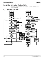
9. Outline of Control (Indoor Unit)
Regarding the outline of control for low-temperature hydrobox (HXY-TA), refer to the service
manual SiUS392016EA.
9.1 Operation
Flowchart
Is
test run in
progress?
Is freeze-
up prevention operation in
progress?
Is
Restart prevention
operation in progress?
(5 min.)
De
w
prevention condition?
Is the
safety device
activated?
Start
Heating Operation
Fan Operation
Cooling Operation
Cooling Operation
Detect louver lock
( )
Run or Stop?
RU
N
indicating lamp: OFF
RU
N
indicating lamp: Blink
Error code: Displayed
RU
N
indicating lamp: OFF
Error mode display: Reset
Thermostat status
S
w
ing flap
S
w
ing flap
Set
w
ind direction
Program dry display: Reset
Program dry operation
A
A
A
Stop
Run
Yes
Yes
Yes
Yes
Yes
Yes
N
o
N
o
N
o
N
o
O
N
OFF
N
o
N
o
N
o
∗
1
Fan
Temp. control
Heating
Cooling
∗
2 Fan : Stop
Louver : Stop
∗
3
∗
4
∗
7
∗
4
∗
6
∗
5
(Option)
OFF
O
N
MF
MF
: OFF
MP
Drain pump kit
MP
Drain pump kit
MP
Drain pump kit
:O
N
MP
Drain pump kit
: O
N
MP
: Closed
Electronic expansion valve
: Capacity control
Electronic expansion valve
: Closed
YE
MA
: OFF
EH
: OFF
EH
Humidifier : OFF
Hu
Humidifier : OFF
Hu
YE
The previous settings of airflo
w
rate,
w
ind direction, and
temperature are displayed.
Is the RU
N
indicating lamp
blinking?
Press the RESET
RU
N
/STOP push
button.
Electronic
expansion valve
Thermostat-O
N
-
operation signal to
outdoor unit: Output
Thermostat-O
N
-
operation signal to
outdoor unit: Output
RU
N
indicating lamp: O
N
Airflo
w
rate display: Displayed
W
ind direction display: Displayed
Temp. setting display: Displayed
Turn O
N
po
w
er supply
Initialize electronic
expansion valve
LED in remote
controller turns O
N
Cyclic operation
w
ith
RU
N
/STOP push button
Fan or Temp.
control?
Cooling or
Heating?
Drain
pump kit
Aux. electric
heater
Aux. electric
heater
De
w
prevention position
Cassette type: P1
Ceiling suspended type: P0
Program dry
O
N
/OFF
Fan:
Operating
w
ith set airflo
w
rate
: OFF after 5-min.
residual operation
: OFF after 5-min.
residual operation
Yes
YE
YE
Summary of Contents for VRV EMERION RXYQ-AATJA
Page 1: ...Service Manual Heat Pump 60 Hz RXYQ AATJA 208 230 V RXYQ AAYDA 460 V SiUS342303E...
Page 410: ...Wiring Diagrams SiUS342303E 403 Part 7 Appendix FXEQ07 09 12 15 18 24PVJU 3D098557A...
Page 411: ...SiUS342303E Wiring Diagrams Part 7 Appendix 404 FXDQ07 09 12 18 24MVJU C 3D050501C...
Page 416: ...Wiring Diagrams SiUS342303E 409 Part 7 Appendix FXHQ12 24 36MVJU 3D048116C...
Page 417: ...SiUS342303E Wiring Diagrams Part 7 Appendix 410 FXAQ07 09 12 18 24PVJU 3D075354F...
Page 424: ...Wiring Diagrams SiUS342303E 417 Part 7 Appendix VAM1200GVJU 3D073270D...


