background image

24

English

12 .  Checking of device and installation conditions

Be sure to check the followings.

For those doing electrical work

Make sure there is no faulty transmission wiring or loosening of a 
nut.

See 9.4. Transmission wiring connection procedure on page 20.

Make sure there is no faulty power wiring or loosening of a nut.

See 9.5. Power wiring connection procedure on page 21.

Has the insulation of the main power circuit deteriorated?
Measure the insulation and check the insulation is above regular 
value in accordance with relevant local and national regulations.

For those doing pipe work

Make sure piping size is correct.

See 7.2. Selection of piping material on page 9 and 7.4. Selec

-

tion of refrigerant branch kits on page 10.

Make sure insulation work is done.
See 11. Pipe insulation.

Make sure there is no faulty refrigerant piping.

See 8. Precautions on refrigerant piping on page 14.

13 . 

Making field settings

To continue the configuration of the outdoor units, it is required to give 

some input to the printed circuit board of the unit. This chapter will 
describe how manual input is possible by operating the push buttons/
DIP switches on the printed circuit board and reading the feedback 
from the 7 segment displays.
For VRV Aurora series it is alternatively possible to make several 

commissioning field settings through a personal computer interface 

(for this, option 999482P3 is required). The installer can prepare the 

configuration (off-site) on PC and afterwards upload the configuration 

to the system. How to connect the cable is described in  

13.3. Connecting the PC configurator to the outdoor unit on 
page 26.

The contents of the actual settings is discussed and explained in 15.2. 
Monitoring function and field settings on page 31.

13 .1 .  Accessing the push buttons on the printed circuit 

board

It is not required to open the complete control box to access the 

push buttons on the printed circuit board and read out the 7 segment 
display (s).

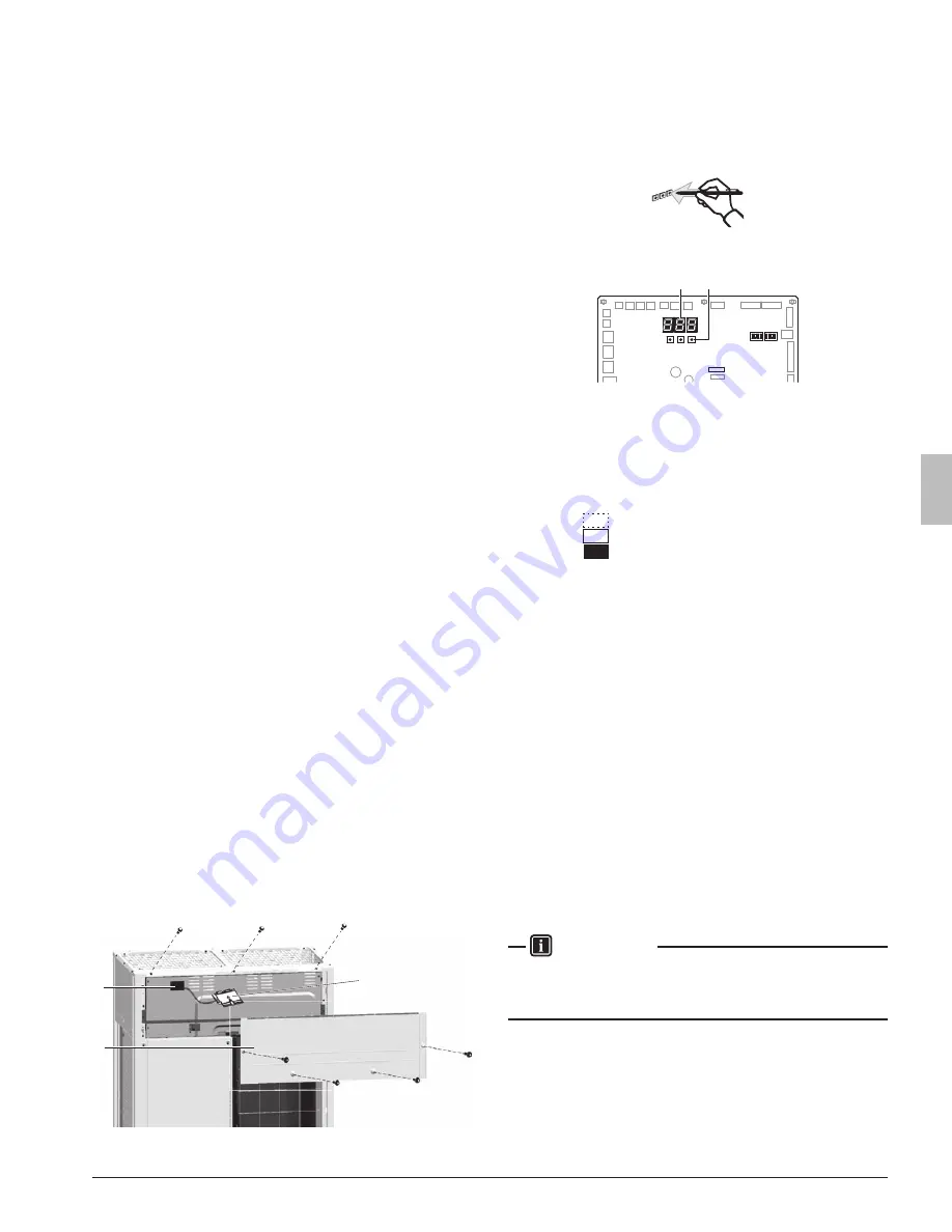
To access you can remove the front panel (see figure). Now you can 
open the inspection door of the control box cover (see figure). You can 

see 3 push buttons and 3 seven-segment displays and DIP switches.

3

1

2

1  Front panel
2 Inspection door
3  Main printed circuit board with 3 seven-segment display 

and 3 push buttons

Operate the switches and push buttons with an insulated stick (such 
as a closed ballpoint pen) to avoid touching of live parts.

Location of the segment displays, buttons and DIP switches:

BS1 BS2

DS1 DS2

BS3

X27A

1

2

BS1

for changing setting mode

BS2, BS3 

for changing field setting

DS1, DS2 

DIP switches

7 segment displays (3

×

)

Push buttons

Segment display indications: 


 Off

  Blinking
  On

13 .2 .  Operating the push buttons and DIP switches on 

the printed circuit board

13 .2 .1 .  Operating the push buttons

By operating the push buttons it is possible to:

• 

Perform special actions (automatic refrigerant charging, test run, etc).

•  Perform field settings (demand operation, low noise, etc).

Below procedure explains how to operate the push buttons to reach 

the required mode in the menu, select the correct setting and modify 
the value of the setting. This procedure can be used any time special 

settings and regular field setting are discussed in this manual (see 
15.2. Monitoring function and field settings on page 31).

Setting definition: [A-B]=C; A=mode; B=setting; C=setting value. A, B 
and C are numerical values for field settings. Parameter C has to be 
defined. It can be a chosen from a set (0, 1, 2, 3, 4, 5, …) or regarded 

as an ON/OFF (1 or 0) depending on the contents. This is informed 

when the field setting is explained (see 15.2. Monitoring function and 
field settings on page 31).

 INFORMATION

During special operation (e.g., automatic refrigerant charging, test 
run, etc.) or when an malfunction happened, information will contain 
letters and numerical values.

Functions of the push button switches which are located on the 

main printed circuit board (A1P)

Turn on the power supply of the outdoor unit and all indoor units. 
When the communication between indoor units and outdoor unit (s) is 
established and normal, the segment indication state will be as follows 
(default situation when shipped from factory):

01_EN_3P477778-3C.indb   24

2/8/2018   14:31:37

Summary of Contents for VRV Aurora RXLQ120TATJU

Page 1: ...JU RXLQ96TATJU RXLQ120TATJU RXLQ144TATJU RXLQ192TATJU RXLQ240TATJU RXLQ72TAYDU RXLQ96TAYDU RXLQ120TAYDU RXLQ144TAYDU RXLQ192TAYDU RXLQ240TAYDU RXLQ72TAYCU RXLQ96TAYCU RXLQ120TAYCU RXLQ144TAYCU RXLQ192...

Page 2: ...must be done in accordance with this installation manual Improper installation could result in water leakage electric shock or fire When installing the unit in a small room take measures to keep the...

Page 3: ...ch as possible Indoor units are for indoor installation only Outdoor units can be installed either outdoors or indoors This unit is for outdoor use Do not install the air conditioner or heat pump in t...

Page 4: ...11 8 Precautions on refrigerant piping 14 8 1 Caution for brazing 14 8 2 Connecting the refrigerant piping 14 8 3 Guidelines for handling stop valve 17 9 Field wiring 18 9 1 Power circuit safety devic...

Page 5: ...below and right where RXLQ 144 240 consists of multiple RXLQ 72 120 single modules as indicated 72 96 120 RXLQ72TATJU TAYDU TAYCU 1 RXLQ96TATJU TAYDU TAYCU 1 RXLQ120TATJU TAYDU TAYCU 1 RXLQ144TATJU TA...

Page 6: ...120TAYDU 144TAYDU 192TAYDU 240TAYDU 72TAYCU 96TAYCU 120TAYCU 144TAYCU 192TAYCU 240TAYCU Max Number of Connectable Indoor Units 12 16 20 25 33 41 Note Values inside brackets are based on connection of...

Page 7: ...ust be strong enough to support the weight of the unit Installation location is flat to prevent vibrations and noise generation and to have sufficient stability The space around the unit is adequate f...

Page 8: ...kes into account improper installation may result in the unit turning over 4 2 Weather related precautions Be sure that the air inlet of the unit is not positioned towards the main wind direction Fron...

Page 9: ...ble refer to the figure below and choose one of the possibilities a b a c d a b a e d e c a b a e d f c a b a e b d c a b a e d f c 1 2 3 5 4 ABCD Sides along the installation site with obstacles Suct...

Page 10: ...ther specifications can be found in the Engineering Data Book 6 Inspecting handling and unpacking the unit 6 1 Inspection At delivery the unit must be checked and any damage must be re ported immediat...

Page 11: ...screw in the founda tion bolts until their length remains 13 16 in 20 mm above the foundation surface A A 13 16 in 20 mm NOTE There are restrictions on the refrigerant pipe connecting order between o...

Page 12: ...which are clean inside and outside and which do not accumulate harmful sulfur oxidants dirt cutting oils moisture or other contamination Foreign materials inside pipes including oils for fabrication m...

Page 13: ...r 295 ft 90 m Outdoor unit capacity type Gas pipe Liquid pipe RXLQ72T type 3 4 in 19 1 mm 7 8 in 22 2 mm 3 8 in 9 5 mm 1 2 in 12 7 mm RXLQ96T type 7 8 in 22 2 mm 1 in 25 4 mm a RXLQ120T type Increase...

Page 14: ...gth pipe length between outdoor 1 and indoor units Equivalent piping length pipe length between outdoor 1 and indoor units Assume equivalent piping length of refnet joint 1 6 ft 0 5 m and refnet heade...

Page 15: ...le 1 3 unit 8 a i 540 ft 165 m Equivalent length 623 ft 2 190 m Total piping length 1640 ft 500 m Example 1 1 a b c d e f g h i j k l m n p 1640 ft 500 m Example 2 1 a b c d e f g h i j k l m n p 1640...

Page 16: ...ft 40 m If the increased pipe size is larger than the pipe size of the main pipe then the pipe size of the main pipe has to be increased as well Increase the pipe size as follows f3 8 f1 2 f1 2 f5 8 f...

Page 17: ...h Dry Nitrogen prevents the creation of large quantities of oxidized film on the inside of the piping An oxidized film ad versely affects valves and compressors in the refrigerating system and prevent...

Page 18: ...lame Liquid pipe stop valve Gas pipe stop valve Protective plate Stop valves mounting plate 5 Cut off the lower part of the smaller pinched piping with an ap propriate tool such as pipe cutters Let th...

Page 19: ...ller field piping 8 2 4 Precautions when connecting piping between outdoor units multiple outdoor units system To connect the piping between outdoor units an optional multi connection piping kit BHFP2...

Page 20: ...Mount the REFNET header so that it branches horizontally 2 Installation of the multi connection piping kit A 1 B 1 C D 15 C 4 3 4 in 120 mm D 19 11 16 in 500 mm Install the joints horizontally so tha...

Page 21: ...g torque refer to 8 3 2 How to use the stop valve Check for refrigerant leaks after tightening the service port cover 9 Field wiring NOTE All field wiring and components must be installed by a license...

Page 22: ...0 90 AWG18 16 AWG18 16 AWG18 16 AWG18 16 AWG18 16 AWG18 16 RXLQ72TAYDU RXLQ96TAYDU RXLQ120TAYDU RXLQ144TAYDU RXLQ192TAYDU RXLQ240TAYDU f3 60Hz f3 60Hz f3 60Hz f3 60Hz f3 60Hz f3 60Hz 460V 460V 460V 46...

Page 23: ...ration Onsite settings can be accomplished by operating the printed circuit board A1P of Master unit NOTE Do not connect the power wiring to terminals for the transmission wiring Doing so would destro...

Page 24: ...make it possible for insects rainwater snow and other ob jects to enter the electrical wiring box which may cause malfunctions Control box cover It causes damp air or water to enter Front side Termin...

Page 25: ...ectrical parts in the control box 10 Air tight test and vacuum drying After finished piping work carry out air tight test and vacuum drying NOTE Always use nitrogen gas for the air tightness test Abso...

Page 26: ...evacuating the system for 2 hours pressurize the system to 375 000 microns vacuum break with nitrogen gas and evacuate the system again using the vacuum pump for 1 hour to 500 microns or less vacuum...

Page 27: ...you can remove the front panel see figure Now you can open the inspection door of the control box cover see figure You can see 3 push buttons and 3 seven segment displays and DIP switches 3 1 2 1 Fron...

Page 28: ...n is the amount of indoor units which are con nected to the system Result mode 1 setting 10 is addressed and selected return value is monitored information To leave the monitoring function push BS1 on...

Page 29: ...on page i To avoid compressor breakdown do not charge the refrigerant more than the specified amount This outdoor unit is factory charged with refrigerant and depending on pipe sizes and pipe lengths...

Page 30: ...0TAYCU RXLQ120TAYCU RXLQ120TAYCU Indoor units FXMQ type 18 1 24 1 30 1 36 2 FXFQ type 36 2 Other 48 1 Liquid piping a f3 4 60 ft e f1 4 15 ft i f3 8 20 ft m f3 8 15 ft r f1 2 10 ft b f5 8 20 ft f f3 8...

Page 31: ...a mixed refrigerant adding it in gas form may cause the refrigerant composition to change preventing normal operation Before charging check whether the refrigerant cylinder is equipped with a siphon t...

Page 32: ...ning by con necting the refrigerant tank only to the liquid stop valve service port open valve C Make sure that all outdoor unit stop valves as well as valves A and C are closed 1 2 3 4 5 6 B C 9 8 10...

Page 33: ...sure to open all stop valves after pre charging the refrigerant Operating with the stop valves closed will damage the compressor 15 Start up and configuration INFORMATION It is important that all info...

Page 34: ...cted time frames The second method is to enable low noise operation based on an external input For this operation an optional acces sory is required 1 2 shows the status of power consumption limitatio...

Page 35: ...is setting will only be effective when the optional external control adaptor DTA104A61 62 is installed Default value 0 To activate this function change 2 12 1 2 18 Fan high static pressure setting In...

Page 36: ...tting Change 2 32 0 1 or 2 in function of required limitation 2 34 Indoor unit fan tap setting Indoor units fan speed limitation related to connection ca pacity and outdoor air temperature for energy...

Page 37: ...Default value 1 Value 2 82 Heating comfort setting 0 Eco 1 Mild default 2 Quick 3 Powerful Change 2 82 0 1 2 or 3 in function of required limitation This setting is used in conjunction with setting 2...

Page 38: ...h to emergency heat if there is a system fault Item Description Min Max Increments Heat Pump Lockout Temp Below this tempera ture heat pump is locked out 15F default 50F 5F Heat Pump Lockout Release d...

Page 39: ...t mode has been set the auto backup func tion will automatically be set This will allow the auxiliary or secondary heat source to be automatically energized in the event of a system failure Error code...

Page 40: ...us under high sensible mode is comfort feeling for the customer The selection method of indoor units is important and has to be considered as the available capacity is not the same as under basic oper...

Page 41: ...base depending on the situ ation When the request from the indoor units becomes more moderate the system will eventually go to the steady state condition which is defined by the operation method above...

Page 42: ...of all indoor units are finished field piping electrical wiring air purge etc See installation manual of the indoor units for details CAUTION Do not insert fingers rods or other objects into the air i...

Page 43: ...d DIP switches on the printed circuit board on page 24 Push BS2 for 5 seconds or more The unit will start test operation The test operation is automatically carried out the outdoor unit display will i...

Page 44: ...ctronic expansion valve malfunction Y5E A7P X8A Check connection on printed circuit board or actuator 31 36 Electronic expansion valve malfunction Y6E A7P X10A Check connection on printed circuit boar...

Page 45: ...S1NPL A1P X31A Check connection on printed circuit board or actuator LC 14 15 Transmission trouble 208 230 460V A3P X6A A1P X28A 575V A4P X6A A1P X28A Check connection 19 20 Transmission trouble 208 2...

Page 46: ...address malfunction inconsistency Check if transmission wired unit amount matches with powered unit amount by monitor mode or wait till initialization is finished UF 01 Auto address malfunction incon...

Page 47: ...in the outdoor unit before starting service operation on the inverter equipment Be careful not to touch the live parts If a fan rotates due to strong wind it may store electricity in the capacitor or...

Page 48: ...exceeded in the unlikely event of major leak in the system and this in accordance to the local applicable regulations and standards Maximum concentration level The maximum charge of refrigerant and t...

Page 49: ...3P477778 3C EM17A024 1801 HT...

Reviews: