


6 Installation
Installer and user reference guide
28
SERHQ020~0 SEHVX20~64BAW
Split packaged air-cooled water chiller
4P508020-1B – 2018.04
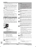
6.9.4
About the electrical wiring
NOTICE
▪ Be sure to keep the power line and transmission line
apart from each other. Transmission wiring and power
supply wiring may cross, but may not run parallel.
▪ Transmission wiring and power supply wiring may not
touch internal piping (except the inverter PCB cooling
pipe) in order to avoid wire damage due to high
temperature piping.
▪ Firmly close the lid and arrange the electrical wires so
as to prevent the lid or other parts from coming loose.
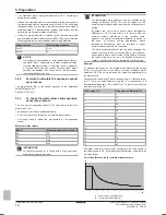
▪ Be sure to follow the limits below. If the unit-to-unit cables are
beyond these limits, it may result in malfunction of transmission:
▪ Maximum wiring length: 1000 m.
▪ Total wiring length: 2000 m.
▪ Transmission wiring to cool/heat selector: 500 m.
▪ Maximum number of independent interconnectable systems: 10.
For the above wiring, always use vinyl cords with 0.75 to 1.25 mm
2
sheath or cables (2-core wires). (3-core wire cables are allowable for
the cooler/heater changeover user interface only.)
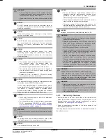
6.9.5
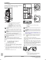
To route and fix the power supply
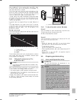
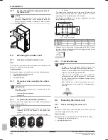
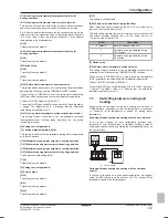
To route and fix the power supply of the outdoor unit
▪ Route the power wiring and the transmission wiring through a
conduit hole.
▪ Route the power wiring though the upper hole in the left side plate,
from the front position of the main unit (through the conduit hole of
the wiring mounting plate), or from a knockout hole in the unit's
bottom plate.
a
b
c
d
e
f g
a
Electric wiring diagram (printed on the back of the electrical
component box lid)
b
Transmission wiring
c
Pipe opening
d
Conduit
e
Power wiring and ground wiring
f
Remove this part before use.
g
Through cover
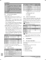
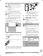
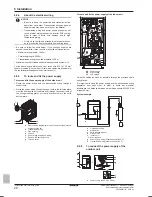
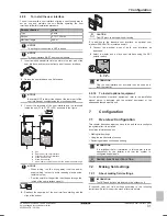
To route and fix the power supply of the indoor unit
LV
LV
PS
PS
LV
PS
HV
PS
Power supply
HV
High voltage
LV
Low voltage
Guide the cables as much as possible through the provided cable
entry glands.
It is important to keep the power supply and the transmission wiring
separated from each other. In order to avoid any electrical
interference the distance between both wirings should ALWAYS be
at least 50 mm.
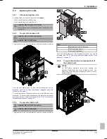
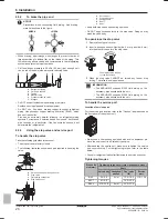
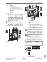
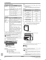
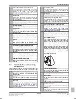
System example
a
b
d
c
B
c
f
e
g
h
a
Field power supply
b
Main switch
c
Earth leakage breaker
d
Outdoor unit
e
Indoor unit
f
User interface
g
Power supply wiring (sheathed cable) (230 V)
h
Transmission wiring (sheathed cable) (16 V)
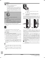
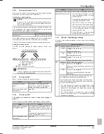
6.9.6
To connect the power supply of the
outdoor unit
L1
L2
L3
N
a
c
d
b
f
e
g
h
i
j
k
a
Power supply (400 V, 3N~ 50 Hz)


