


7 Commissioning
Installer reference guide
22
RZQG7 RZQG71~12 RZQG140L7Y1L
Split system air conditioners
4P473074-1A – 2019.04
There are NO
damaged components
or
squeezed
pipes
on the inside of the indoor and outdoor units.
There are NO
refrigerant leaks
.
The correct pipe size is installed and the
pipes
are
properly insulated.
The
stop valves
(gas and liquid) on the outdoor unit are
fully open.
7.4
To perform a test run
This task is only applicable when using the BRC1E52 user interface.
▪ When using BRC1E51, see the installation manual of the user
interface.
▪ When using BRC1D, see the service manual of the user interface.
NOTICE
Do not interrupt the test run.
INFORMATION
Backlight.
To perform an ON/OFF action on the user
interface, the backlight does not need to be lit. For any
other action, it needs to be lit first. The backlight is lit for
±30 seconds when you press a button.
1
Perform introductory steps.
#
Action
1
Open the liquid stop valve and gas stop valve by
removing the cap and turning counterclockwise with a
hex wrench until it stops.
2
Close the service cover to prevent electric shocks.
3
Turn ON power for at least 6 hours before starting
operation to protect the compressor.
4
On the user interface, set the unit to cooling operation
mode.
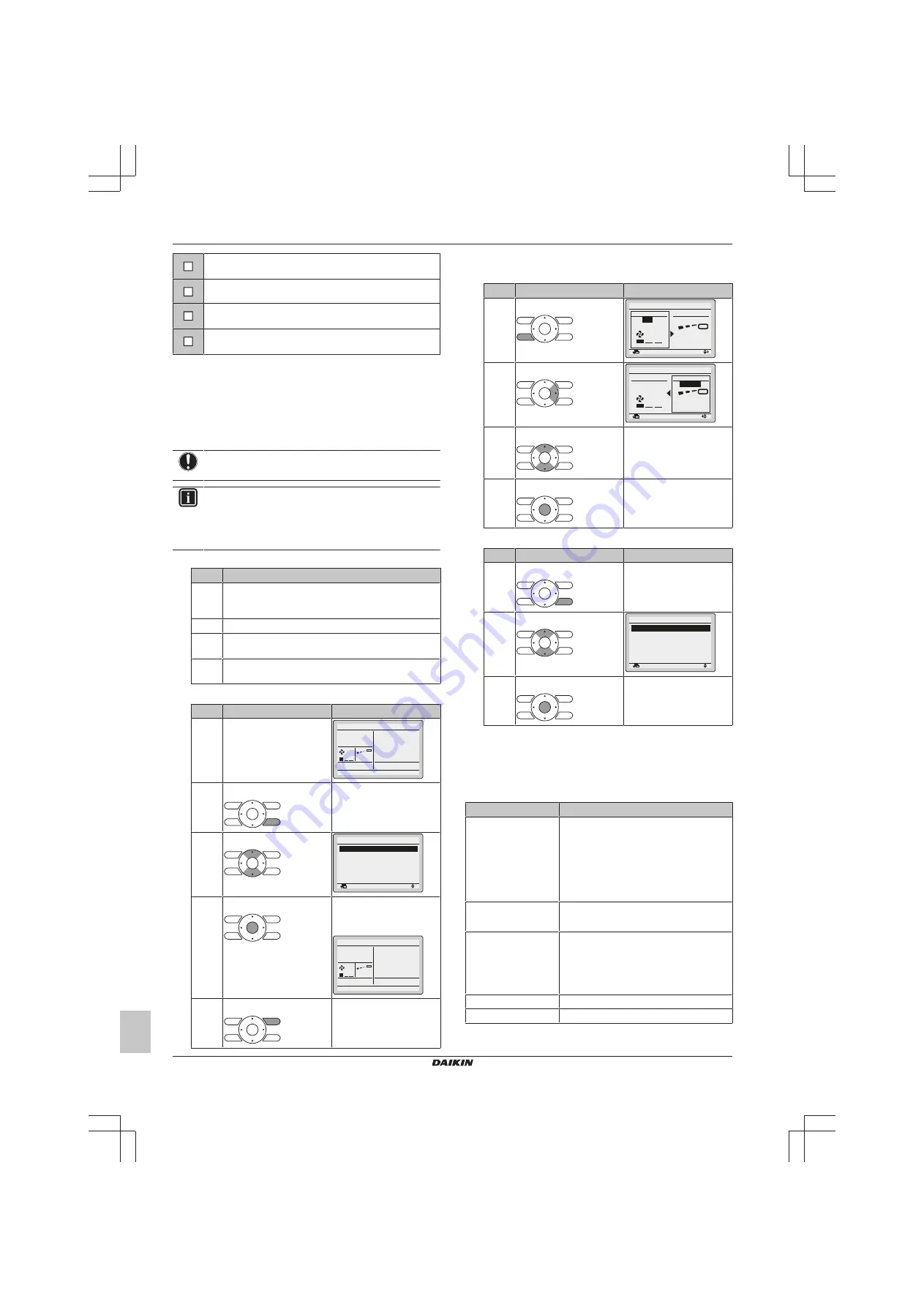
2
Start the test run.
#
Action
Result
1
Go to the home menu.
Cool
Set to
28
°C
2
Press at least 4 seconds.
The Service Settings menu
is displayed.
3
Select Test Operation.
Return
Setting
Service Settings 1/3
Test Operation
Maintenance Contact
Field Settings
Demand
Min Setpoints Differential
Group Address
4
Press.
Test Operation is
displayed on the home
menu.
Cool
Return
Setting
Test Operation
5
Press within 10 seconds.
Test run starts.
3
Check operation for 3 minutes.
4
Check operation of the airflow direction.
#
Action
Result
1
Press.
Return
Setting
Return
Setting
Air Volume/direction
Air Volume
Direction
Position 0
Low
2
Select Position 0.
Return
Setting
Return
Setting
Air Volume/direction
Air Volume
Direction
Low
Position 0
3
Change the position.
If the airflow flap of the
indoor unit moves,
operation is OK.
If not, operation is not OK.
4
Press.
The home menu is
displayed.
5
Stop the test run.
#
Action
Result
1
Press at least 4 seconds.
The Service Settings menu
is displayed.
2
Select Test Operation.
Return
Setting
Service Settings 1/3
Test Operation
Maintenance Contact
Field Settings
Demand
Min Setpoints Differential
Group Address
3
Press.
The unit returns to normal
operation, and the home
menu is displayed.
7.5
Error codes when performing a
test run
If the installation of the outdoor unit has NOT been done correctly,
the following error codes may be displayed on the user interface:
Error code
Possible cause
Nothing displayed
(the currently set
temperature is not
displayed)
▪ The wiring is disconnected or there is a
wiring error (between power supply and
outdoor unit, between outdoor unit and
indoor units, between indoor unit and
user interface).
▪ The fuse on the outdoor unit PCB has
blown out.
E3, E4 or L8
▪ The stop valves are closed.
▪ The air inlet or air outlet is blocked.
E7
There is a missing phase in case of three-
phase power supply units.
Note:
Operation will be impossible. Turn
OFF the power, recheck the wiring, and
switch two of the three electrical wires.
L4
The air inlet or air outlet is blocked.
U0
The stop valves are closed.


