background image

8

English

•  When piping work is complete, it is necessary to perform a pressure test 

and evacuate system with a vacuum pump.

•  If using additional refrigerant, purge the air from the refrigerant pipes and 

indoor unit using a vacuum pump, then charge additional refrigerant.

• 

Use a hexagonal wrench (3/16 inch (4mm)) to operate the stop valve rod.

•  All refrigerant pipe joints should be tightened with a torque wrench to the 

specified tightening torque.
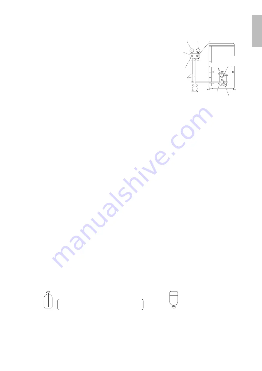
Compound 
pressure gauge

Pressure 
meter

High-pressure 
valve

Low-pressure 
valve

Vacuum pump

Service port

Liquid 
stop 
valve

Valve caps

Gas stop valve

Charging 
hoses

Gauge 
manifold

1) Pressurize the liquid pipe and gas pipe from the service ports of each stop valve to 550psi (3.8MPa) (do not pressurize 

more than 550psi (3.8MPa)) for 1 hour minimum, 24 hours recommended. If there is a pressure drop, check for leaks, 
make repairs and perform the pressure test again.

2) Connect the gauge manifold’s charging hose to the gas stop valve’s service port.
3) Fully open the low-pressure valve (Lo) on the gauge manifold and fully close the high-pressure valve (Hi). 

(High-pressure valve will require no further operation.)

4) 

Evacuate system using vacuum pump to below 500 microns for 1 hour minimum.

5) Close the low-pressure valve (Lo) on the gauge manifold and stop vacuum pumping. 

(Maintain this condition for a few minutes to make sure that the compound pressure gauge pointer does not swing 
back.)*

1

6) Remove the valve caps from the liquid stop valve and gas stop valve.
7) 

To open the liquid stop valve, turn the rod of the valve 90° counter-clockwise using a hexagonal wrench.


Close it after 5 seconds, and check for gas leakage. 

Using soapy water, check for gas leakage from the indoor unit’s flare and outdoor unit’s flare and valve rods.


After the check is complete, wipe all soapy water off.

8) Disconnect the charging hoses from the service port for the gas stop valve, then fully open the liquid and gas stop valves. 

(Do not attempt to turn the valve rods further than they can go.)

9) 

Tighten the valve caps and service port caps for the liquid and gas stop valves with a torque wrench to the specified 

torques. 
Refer to 

“4. Refrigerant piping”

 on page 6 for details.

*

1

  If the compound pressure gauge pointer swings back, the refrigerant may have water content or there may be a loose 

pipe joint. 
Check all pipe joints and retighten nuts as needed, then repeat steps 3) through 5).

6. 

Refilling refrigerant

Check the type of refrigerant to be used on the machine nameplate.

Precautions when adding R410A
Fill from the liquid pipe in liquid form.

R410A is a mixed refrigerant, so adding it in gas form may cause the refrigerant composition to change, preventing normal 

operation.

• 

Before filling, check whether the cylinder has a siphon attached or not. (It should have something like “liquid filling siphon 

attached” displayed on it.)

Filling a cylinder with an attached siphon

Stand the cylinder upright when filling.

There is a siphon pipe inside, so the cylinder 

need not be upside-down to fill with liquid.

Filling other cylinders

Turn the cylinder 

upside-down when filling.

•  Be sure to use the R410A tools to ensure pressure and to prevent foreign objects entering.

English

01_EN_3P572321-2.indd   8

2019/07/02   16:31:45

Summary of Contents for RXL18UMVJU

Page 1: ...nglish Français Español MODELS RXL18UMVJU RXL24UMVJU DAIKIN ROOM AIR CONDITIONER INSTALLATION MANUAL R410A Split Series Installation manual Manuel dinstallation Manual de instalación Manuel dinstallation ...

Page 2: ...ation hazard could occur leading to serious injury or death Do not ground units to water pipes gas pipes telephone wires or lightning rods as incomplete grounding can cause a severe shock hazard resulting in severe injury or death Additionally grounding to gas pipes could cause a gas leak and potential explosion causing severe injury or death If refrigerant gas leaks during installation ventilate ...

Page 3: ...m getting into the system b Tight R410A does not contain any chlorine does not destroy the ozone layer and does not reduce the earth s protection again harmful ultraviolet radiation R410A can contribute to the greenhouse effect if it is released Therefore take proper measures to check for the tightness of the refrigerant piping installation Read the chapter Refrigerant Piping Work and follow the p...

Page 4: ...en the life of the air conditioner 8 Since water will flow from the drain of the outdoor unit do not place under the unit anything which must be kept away from moisture NOTE Cannot be installed suspended from a ceiling or stacked CAUTION When operating the air conditioner in a low outdoor ambient temperature be sure to follow the instructions described below To prevent exposure to wind install the...

Page 5: ...3m in order to avoid noise from the outdoor unit and vibration Mechanical noise and vibration may occur depending on how the unit is installed and the environment in which it is used 10ft 3m O D 5 8 inch 15 9mm O D 1 2 inch 12 7mm 65 5 8ft 20m 98 1 2ft 30m Min allowable piping length Foot bolt hole centers From unit s side Allow 11 13 16 300mm of work space below the ceiling surface 9 13 16 250mm ...

Page 6: ... orientation of the outdoor unit outlet side or use the air direction adjustment grille sold separately Outdoor Unit Installation 1 Installing the outdoor unit When installing the outdoor unit refer to Precautions for Selecting a Location and the Outdoor Unit Installation Diagram If drain work is necessary follow the procedures in 2 Drain work 2 Drain work CAUTION In cold areas do not use a drain ...

Page 7: ...le Make sure that the flare nut is fitted Set exactly at the position shown below Flaring A Die A 0 0 020 inch 0 0 5mm Clutch type Flare tool for R410A 0 039 0 059 inch 1 0 1 5mm Clutch type Rigid type 0 059 0 079 inch 1 5 2 0mm Wing nut type Imperial type Conventional flare tool Cut exactly at right angles Remove burrs 4 Refrigerant piping CAUTION Use the flare nut fixed to the main unit This is to ...

Page 8: ...ain Gas side Piping size O D 5 8 inch 15 9mm O D 1 4 inch 6 4mm 1 15 16 inch 50mm or more 1 3 16 inch 30mm or more 0 039 inch 1 0mm C1220T O 0 031 inch 0 8mm C1220T O I D 5 8 13 16 inch 16 20mm I D 5 16 13 32 inch 8 10mm 13 32 inch 10mm Min Minimum bend radius Piping thickness Thermal insulation size Thermal insulation thickness Liquid side O D 1 2 inch 12 7mm 1 9 16 inch 40mm or more 0 031 inch 0...

Page 9: ...alve 7 To open the liquid stop valve turn the rod of the valve 90 counter clockwise using a hexagonal wrench Close it after 5 seconds and check for gas leakage Using soapy water check for gas leakage from the indoor unit s flare and outdoor unit s flare and valve rods After the check is complete wipe all soapy water off 8 Disconnect the charging hoses from the service port for the gas stop valve t...

Page 10: ...ound crimp style terminal Screw A Arrow view A When connecting the inter unit wires to the terminal block using a single core wire be sure to curl the end of the lead Improper work may cause heat and fire Strip wire end to this point Excessive strip length may cause electric shock or current leakage Stripping wire at terminal block Good Wrong Good Wrong Do not turn on the circuit breaker until all...

Page 11: ... and off when using facility settings Do not place humidifiers or other items which might raise the humidity in rooms where facility settings are being used A humidifier might cause dew condensation from the indoor unit outlet vent Activating the facility setting sets the indoor fan tap to the highest position Notify the user about this This function is designed for facilities such as equipment or...

Page 12: ...ation For FDMQ models Using the indoor unit s remote controller For wired remote controller 1 Set to COOL operation using the remote controller 2 Press and hold the Cancel button for 4 seconds or longer Service settings menu is displayed 3 Select Test Operation in the service settings menu and press the Menu OK button Basic screen returns and Test Operation is displayed at the bottom 4 Press the O...

Page 13: ...o stop the operation press Trial Operation and Testing When trial operation is conducted directly after the circuit breaker is turned on in some cases no air will be output for about 15 minutes in order to protect the air conditioner 1 Trial operation and testing Refer to the installation manual for the indoor unit 2 Test items Test items Symptom Check Indoor and outdoor units are installed secure...

Page 14: ...Two dimensional bar code is a manufacturing code 3P572321 2 M18B296 1907 HT ...

Reviews: