background image

3

1

7

•  VRV Systems • Outdoor Units  

30

•  Outdoor Units • VRV HEAT RECOVERY • REYHQ16-24P  

7

Wiring  diagram

7 - 1

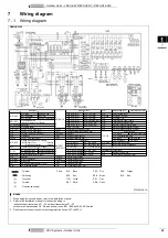
Wiring diagram

REMHQ12P9

2TW29146-1A

NOTES

1

When using the option adaptor, refer to the installation manual

2

Refer to the installation manual, for connection wiring to 
indoor-outdoor transmission F1 - F2, outdoor transmission F1 - F2,
outdoor-multi transmission Q1 - Q2 and on how to use BS1~BS5 and DS1, DS2 switch.

3

Do not operate the unit by short-circuiting protection device S1PH~S3PH

Indoor unit

K1R~K11R

Magnetic relay

V1R

Diode bridge (A3P)

Power module (A4P,A8P)

A1P~A8P

A1P: Main

A4P,A8P: Fan

K1R: K2M (A1P)

K1R: Y5S (A5P)

V2R

Power module (A3P)

A2P: Noise filter

A5P: Sub

K2R: K3M (A1P)

K2R: Y6S (A5P)

X1A~X4A

Connector (M1F, M2F)

A3P: Inverter

A6P,A7P: Current sensor

K3R: Y1S (A1P)

K4R: Y2S (A1P)

X5A

Connector (Y1E)

BS1~BS5

Push button switch
(Mode, Set, Return, Test, Reset)

K5R: Y3S (A1P)

K5R: (for option) (A5P)

X1M

Terminal strip (Power supply)

K6R: Y7S (A5P)

K7R: E1HC (A1P)

X1M

Terminal strip (Control) (A1P)

C1, C63, C66

Capacitor

K8R: E2HC (A1P)

K9R: E3HC (A1P)

Y1E

Electronic expansion valve (Main)

E1HC~E3HC

Crankcase heater

K11R: Y4S (A1P)

Y2E

Electronic expansion valve (Charge)

F1U, F2U

Fuse (T, 3.15A, 250V) (A1P)

Q1RP

Reverse phase detection circuit

Y3E

Electronic expansion valve (Subcool)

F1U

Fuse (T, 3.15A, 250V) (A5P)

R10

Resistor (current sensor) (A4P,A8P)

Y1S~Y3S

Solenoid valve

F1U

Fuse (8A, DC650V) (A4P,A8P)

R50, R59

Resistor

Y1S: RMTG

Y2S:  4 way valve (pipe)

F5U

Field fusef

R90

Resistor (current sensor)

Y3S: 4 way valve (H/E Gas)

F400U

Fuse (T, 63A, 250V) (A2P)

R95

Resistor (current limiting)

Y4S: RMTL

Y5S: Hots gas

H1P~H8P

Pilotlamp (service monitor -orange)
[H2P] Prepare, Test - - - -  - - - - - -  Flickering
          Malfunction detection - - - - - - Light up

R1T~R9T
R31T~R33T

Thermistor

Y6S: EV bypass 

Y7S: RMTO

R1T: Air (A1P)

R4T: H/E Deicer

Z1C~Z10C

Noise filter (ferrite core)

R1T: Fin (A3P)

R5T: Sub cool H/E gas

Z1F

Noise filter (with surge absorber)

HAP

Pilotlamp (service monitor - orange)

R2T: H/E Gas

R6T: Sub cool H/E liq

K1~K4

K1: Magnetic relay

K2: Magnetic contactor (M1C)

R31T: M1C Discharge R7T: H/E Liquid

Connector for optional parts

K3: Magnetic relay

K4: Magnetic contactor (M1C)

R32T: M2C Discharge R8T: Suction

X7A

Operation output (A5P)

K2M, K3M

Magnetic contactor (M2C, M3C)

R33T: M3C Discharge R9T: Liquid

X9A

Power supply (ADAPTER) (A5P)

L1R

Reactor

S1NPH

Pressure sensor (High)

M1C~M3C

Motor (Compressor)

S1NPL

Pressure sensor (Low)

M1F, M2F

Motor (Fan)

S1PH~S3PH

Pressure switch (High)

PS

Switching power supply (A1P, A3P)

SD1

Safety devices input

Q1DI

Earth leakage breaker

T1A

Current sensor (A6P, A7P)

: Terminal

Colors:

BLK:

Black

PNK:

Pink

ORG:

Orange

: Field wiring

RED:

Red

BRN:

Brown

BLU:

Blue

: Connector

YLW:

Yellow

GRY:

Grey

: Terminal

WHT:

White

GRN:

Green

: Protective eart (screw)

POWER SUPPLY

Position in switch box

Note 5

TO

IN/D

UNIT

Male connector: BLU
Female connector: WHT

Front layer

12 HP

TO

OUT/D

UNIT

TO

MULTI

UNIT

MALE CONNECTOR: BLK
FEMALE CONNECTOR: WHT

Rear layer

indoor

(F1)(F2)

outdoor

(F1)(F2)

outdoor

(01)(02)

Male conn: RED
Female conn: WHT

Detail of M1C~M3C

Detail of M1C~M3C

El. compo. box

Position of M1~3C,M1,2F

Summary of Contents for REYHQ16-24P Series

Page 1: ...ables 6 Combination table 6 Cooling capacity tables 7 Heating capacity tables 15 Capacity correction factor 23 5 Dimensional drawing centre of gravity 27 Dimensional drawing 27 Centre of gravity 28 6...

Page 2: ...2 088 Nr of Rows 54 54 54 54 Fin Pitch mm 2 2 2 2 Nr of Passes 18 18 18 21 18 21 21 21 Face Area m 2 112 2 112 2 112 2 481 2 112 2 481 2 481 2 481 Nr of Stages 2 2 2 2 Tube type Hi XSS 8 Fin Fin type...

Page 3: ...erature Capacity Control Method Inverter controlled Capacity Control 100 Safety devices HPS Fan motor driver overload protector Over current relay Inverter overload protector PC board fuse Standard Ac...

Page 4: ...rcuit breaker and the ground fault circuit interrupter earth leakage circuit breaker MSC means the maximum current during start up of the compressor Maximum allowable voltage range variation between p...

Page 5: ...al technical standard setting the limits for voltage changes voltage fluctuations and flicker in public low voltage supply systems for equipment with rated 75A 2 European International technical stand...

Page 6: ...RQ23M64T o o o o o KHRQ23M75T o o Ountdoor unit multipiping connection kit for H R BHFQ23P907 o BHFQ23P1357 o Central drain pan kit KWC26C280 o o o See note 4 See note 4 KWC26C450 o o See note 4 See n...

Page 7: ...V Systems Outdoor Units 6 Outdoor Units VRV HEAT RECOVERY REYHQ16 24P 4 Capacity tables 4 1 Combination table REYHQ P 4TW31481 1 UNIT REMQ8P9 REMQ10P8 REMHQ12P8 REYHQ16P 2 REYHQ20P 1 1 REYHQ22P 1 1 RE...

Page 8: ...7 50 4 8 4 51 1 8 4 51 7 8 5 53 0 8 5 54 4 8 6 25 36 4 5 59 43 5 7 2 49 7 8 7 50 3 8 8 51 0 8 8 52 3 8 9 53 6 9 0 27 36 4 5 97 43 5 7 7 49 0 9 1 49 6 9 2 50 3 9 2 51 6 9 3 52 9 9 4 29 36 4 6 37 43 5 8...

Page 9: ...2 69 25 4 3 21 29 5 3 76 31 5 4 04 33 5 4 34 37 6 4 94 41 7 5 56 20 21 3 2 74 25 4 3 27 29 5 3 83 31 5 4 12 33 5 4 42 37 6 5 04 41 7 5 71 21 21 3 2 76 25 4 3 30 29 5 3 87 31 5 4 16 33 5 4 46 37 6 5 1...

Page 10: ...1 64 4 11 2 66 0 11 3 67 7 11 4 25 45 4 7 40 54 1 9 5 61 8 11 6 62 7 11 6 63 5 11 7 65 1 11 8 66 7 11 9 27 45 4 7 90 54 1 10 2 60 9 12 1 61 7 12 1 62 6 12 2 64 2 12 3 65 8 12 4 29 45 4 8 43 54 1 10 9...

Page 11: ...51 9 7 22 18 26 5 3 56 31 6 4 25 36 7 4 98 39 2 5 35 41 7 5 74 46 8 6 54 51 9 7 36 20 26 5 3 62 31 6 4 32 36 7 5 07 39 2 5 46 41 7 5 85 46 8 6 67 51 9 7 56 21 26 5 3 65 31 6 4 36 36 7 5 12 39 2 5 51 4...

Page 12: ...8 12 8 70 7 12 9 72 5 13 0 74 3 13 1 25 49 8 8 52 59 4 11 0 67 9 13 3 68 8 13 4 69 7 13 4 71 5 13 6 73 3 13 7 27 49 8 9 10 59 4 11 7 66 9 13 9 67 8 13 9 68 7 14 0 70 5 14 1 72 3 14 3 29 49 8 9 7 59 4...

Page 13: ...38 57 0 8 31 18 29 1 4 10 34 7 4 89 40 3 5 73 43 1 6 16 45 9 6 61 51 4 7 52 57 0 8 47 20 29 1 4 17 34 7 4 98 40 3 5 84 43 1 6 28 45 9 6 74 51 4 7 67 57 0 8 71 21 29 1 4 21 34 7 5 02 40 3 5 89 43 1 6 3...

Page 14: ...8 76 4 13 9 77 4 14 0 79 3 14 1 81 3 14 2 25 54 3 9 2 64 7 11 8 74 3 14 4 75 3 14 5 76 3 14 6 78 3 14 7 80 2 14 9 27 54 3 9 8 64 7 12 6 73 2 15 0 74 2 15 1 75 2 15 2 77 2 15 3 79 1 15 5 29 54 3 10 4...

Page 15: ...3 62 1 8 9 18 31 7 4 41 37 8 5 26 43 9 6 16 46 9 6 63 50 0 7 10 56 0 8 1 62 1 9 1 20 31 7 4 48 37 8 5 35 43 9 6 27 46 9 6 75 50 0 7 24 56 0 8 2 62 1 9 4 21 31 7 4 52 37 8 5 40 43 9 6 33 46 9 6 82 50 0...

Page 16: ...6 3 10 8 36 3 11 0 36 2 11 2 36 1 11 6 9 5 10 0 37 4 10 21 37 3 10 6 37 2 11 0 37 1 11 2 37 1 11 4 37 0 11 8 8 5 9 1 38 2 10 4 38 1 10 7 38 0 11 1 37 9 11 3 37 9 11 5 37 8 11 9 7 0 7 6 39 6 10 6 39 5...

Page 17: ...8 11 0 35 9 12 6 35 9 12 9 35 0 12 7 33 9 12 2 32 8 11 7 30 5 10 7 9 5 10 0 36 8 12 7 36 7 13 0 35 0 12 3 33 9 11 8 32 8 11 4 30 5 10 4 8 5 9 1 37 6 12 8 37 3 12 9 35 0 12 0 33 9 11 5 32 8 11 1 30 5...

Page 18: ...12 9 44 4 13 4 9 5 10 0 45 9 11 7 45 8 12 2 45 7 12 6 45 6 12 9 45 6 13 1 45 4 13 6 8 5 9 1 46 9 11 9 46 8 12 4 46 7 12 8 46 6 13 0 46 5 13 3 46 4 13 7 7 0 7 6 48 6 12 2 48 4 12 6 48 3 13 1 48 3 13 3...

Page 19: ...11 0 44 1 14 6 44 0 14 9 43 8 15 1 42 3 14 5 40 9 13 9 38 1 12 8 9 5 10 0 45 2 14 7 45 1 15 0 43 8 14 7 42 3 14 1 40 9 13 5 38 1 12 5 8 5 9 1 46 1 14 8 46 0 15 1 43 8 14 3 42 3 13 7 40 9 13 2 38 1 12...

Page 20: ...4 9 48 4 15 2 48 3 15 7 9 5 10 0 49 9 13 7 49 8 14 2 49 7 14 8 49 6 15 1 49 5 15 4 49 4 15 9 8 5 9 1 51 0 13 9 50 9 14 4 50 8 15 0 50 7 15 3 50 6 15 5 50 5 16 1 7 0 7 6 52 9 14 3 52 8 14 8 52 6 15 3 5...

Page 21: ...8 11 0 48 0 17 1 47 9 17 5 47 8 17 8 46 7 17 4 45 2 16 7 42 1 15 4 9 5 10 0 49 1 17 3 49 0 17 6 48 3 17 6 46 7 16 9 45 2 16 3 42 1 14 9 8 5 9 1 50 2 17 4 50 1 17 7 48 3 17 1 46 7 16 5 45 2 15 8 42 1 1...

Page 22: ...17 1 56 5 17 3 56 3 17 9 9 5 10 0 58 2 15 8 58 1 16 4 58 0 17 0 57 9 17 3 57 8 17 6 57 7 18 1 8 5 9 1 59 5 16 1 59 3 16 6 59 2 17 2 59 1 17 5 59 0 17 7 58 9 18 3 7 0 7 6 61 6 16 4 61 4 17 0 61 3 17 5...

Page 23: ...17 8 45 8 16 4 9 8 11 0 56 0 19 3 55 9 19 7 52 5 18 2 50 8 17 5 49 1 16 8 45 8 15 5 9 5 10 0 57 3 19 5 55 9 19 1 52 5 17 7 50 8 17 0 49 1 16 4 45 8 15 1 8 5 9 1 58 5 19 6 55 9 18 6 52 5 17 3 50 8 16 6...

Page 24: ...is 90m or more the diameter of the main liquid pipes outdoor unit branch sections must be increased When level difference is 50m or more the diameter of the main gas and liquid pipes outdoor unit bra...

Page 25: ...3 1 4 VRV Systems Outdoor Units 24 Outdoor Units VRV HEAT RECOVERY REYHQ16 24P 4 Capacity tables 4 4 Capacity correction factor J J...

Page 26: ...uid pipes outdoor unit branch sections must be increased When level difference is 50m or more the diameter of the main gas and liquid pipes outdoor unit brach sections must be increased Diameter of ab...

Page 27: ...3 1 4 VRV Systems Outdoor Units 26 Outdoor Units VRV HEAT RECOVERY REYHQ16 24P 4 Capacity tables 4 4 Capacity correction factor H H B J H B J...

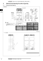
Page 28: ...22 5 mm Oblong holes foundation bolt hole No Parts name Remarks 4 Pressure equalizer pipe connection port 19 1 Brazing connection See note 2 5 Grounding terminal inside of switch box M8 6 Power cord r...

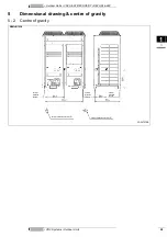
Page 29: ...ERY REYHQ16 24P 5 Dimensional drawing centre of gravity 5 2 Centre of gravity REMHQ12P8 3D057578B Center of foundation bolt hole Center of foundation bolt hole Center of foundation bolt hole Center of...

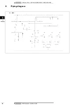
Page 30: ...Outdoor Units VRV HEAT RECOVERY REYHQ16 24P 1 6 VRV Systems Outdoor Units 29 6 Piping diagram H 2P8 J...

Page 31: ...valve pipe F5U Field fusef R90 Resistor current sensor Y3S 4 way valve H E Gas F400U Fuse T 63A 250V A2P R95 Resistor current limiting Y4S RMTL Y5S Hots gas H1P H8P Pilotlamp service monitor orange H...

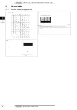
Page 32: ...erates 2 Sound pressure level is a relative value depending on the distance and acoustic environment For more details please refer to sound level drawings 3 Mentioned values are theoretical values bas...

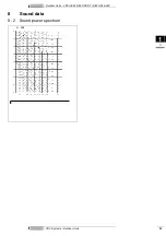
Page 33: ...3 1 8 VRV Systems Outdoor Units 32 Outdoor Units VRV HEAT RECOVERY REYHQ16 24P 8 Sound data 8 2 Sound power spectrum H 2P8...

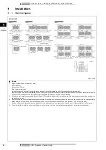
Page 34: ...than are catered for in the above patterns your layout should take account of the possibility of short circuits 4 The units should be installed to leave insufficient space at the front for the on sit...

Page 35: ...is built shall have rough finish 4 A drain ditch shall be made around the foundation to thoroughly drain water from the equipment installation area 5 When installing the equipment on a roof the floor...

Page 36: ...pipe length Pipe length from first refrigerant branch kit either refnet joint or refnet header to indoor unit 40 m See note 2 Example unit 8 b c d e s 40 m Example unit 6 b l 40 m unit 8 m n p 40 m Ex...

Page 37: ...1 0 kg X 1 x 22 2 x0 37 X 2 x 19 1 x0 26 X 3 x 15 9 x0 18 X 4 x 12 7 x0 12 X 5 x 9 5 x0 059 X 6 x 6 4 x0 022 A B x 1 02 REY H Q A 1 0 kg 1 5 kg 2 0 kg 2 5 kg 3 0 kg 3 5 kg 4 0 kg 4 5 kg REYHQ 16 Hp 2...

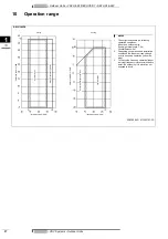
Page 38: ...on Operation range NOTES 1 These figures assume the following operation conditions Indoor and outdoor units Equivalent pipe length 7 5m Level difference 0m 2 Depending on operation and installation co...

Reviews: