IM 1287-4 • REBEL APPLIED ROOFTOP 126 www.DaikinApplied.com
Unit Maintenance
Unit Location and Clearances
While the cabinet location is normally selected by the architect,
builder, or installer, before installation ensure that the following
requirements are met before final installation:
1. Do not install unit where it may exposed to potentially
explosive or flammable vapors.
2. Do not locate unit in areas where corrosive vapors (such
as chlorinated, halogenated, or acidic) are present in
the atmosphere or can be mixed with combustion air
entering furnace.
3. Cabinet location must provide access to all doors and
panels and allow adjustment and service of the furnace.
4. Cabinet location must provide an adequate, unimpeded
supply of fresh air for combustion.
5. Flue discharge should be at least 120 inches away
from any opening or other equipment through which
combustion products could enter the building
6. Clearance from combustibles to be no less than as listed
below:
a. Furnace access side ....................... 18 in (914 mm)
b. All other sides .................................... 6 in (152 mm)
c. Flue to any combustible surface...... 18 in (914 mm)
Do not use this package heater if any part has been under
water. Immediately call a qualified service technician to inspect
the heater and any gas control which has been under water.
If the 23rd digit in the model number is a “G”, the rooftop unit
was furnished with a factory installed natural gas furnace
(Example: DPSA.....GG3KE). If the 23rd digit in the model
number is a “P”, the rooftop unit was furnished with a factory
installed propane furnace. The Rebel Applied commercial
rooftop units are available in a variety of furnace capacity
and turndown configurations. Reference the DPSA Gas
Furnace Capacity Data section below for configuration-
specific information. DPSA packaged gas heat rooftop units
are designed for outdoor non-residential installations only.
Furnaces to be supplied configured for natural gas OR LP only.
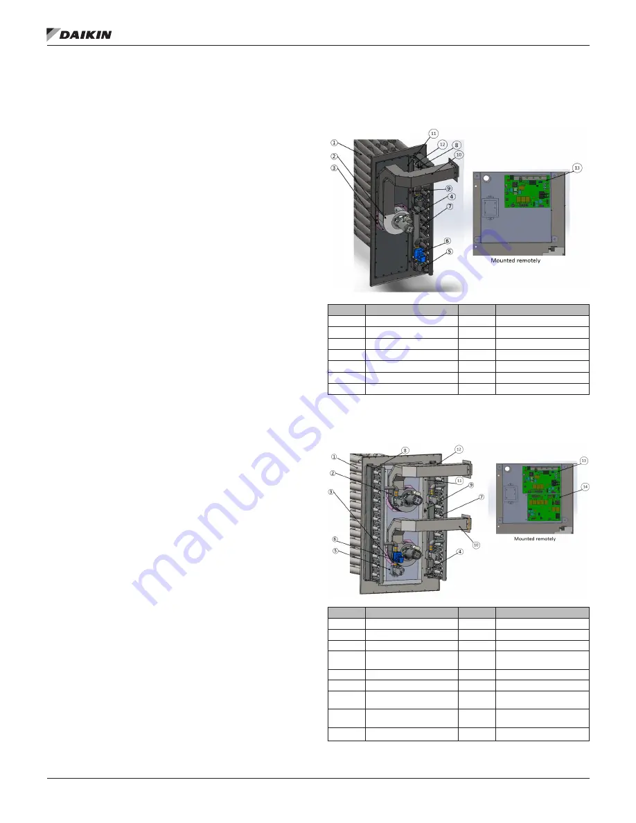
DPSA gas heat furnaces consist of a 439 stainless steel
tubular heat exchanger, in-shot burner manifold with gas valve,
induced combustion blower, gas heat DDC control module, and
all operational safeties. The safety switches include a high-limit
temperature switch, a combustion blower proof of airflow, and
the flame roll-out switch (see
) .
Figure 170: Typical Gas Heat Section Assembly and
Component Identification for Single Flue Furnaces (10:1
600 MBH model shown)
Item
Description
Item
Description
1
Heat Exchanger
8
Rollout switch
2
Inducer blower
9
High limit switch
3
Inducer orifice plate
10
Flue
4
Igniter
11
Pressure switch
5
Gas safety valve
12
Flame sensor
6
Modulating valve
13
Control board
7
In-shot burner
14
Transformer
Figure 171: Typical Gas Heat Section Assembly and
Component Identification for Double Flue Furnaces (10:1
1125 MBH model shown)
Item
Description
Item
Description
1
Heat Exchanger
10
Flue
2
Inducer blower
11
Pressure switch
3
Inducer orifice plate
12
Flame sensor
4
Igniter
13
VB 1285 modulating control
board
5
Gas safety valve
14
VB1287 staged control board
6
Modulating valve
15
Transformer
7
In-shot burner
16
High Temp limit interlock
relay
8
Rollout switch
17
On/off solenoid valve (not
pictured)*
9
High limit switch
*On/off solenoid valve only present in 800 MBH 10:1 or 6:1 furnaces
Summary of Contents for Rebel Applied DPSA
Page 147: ...Figure 181 600 MBH 5 1 Modulation 400 MBH and 600 MBH 10 1 Modulation ...
Page 160: ......
Page 161: ......


