Installation and Maintenance Manual IM 1102
Group:
Applied Air Systems
Part Number:
IM 1102
Date:
October 2010
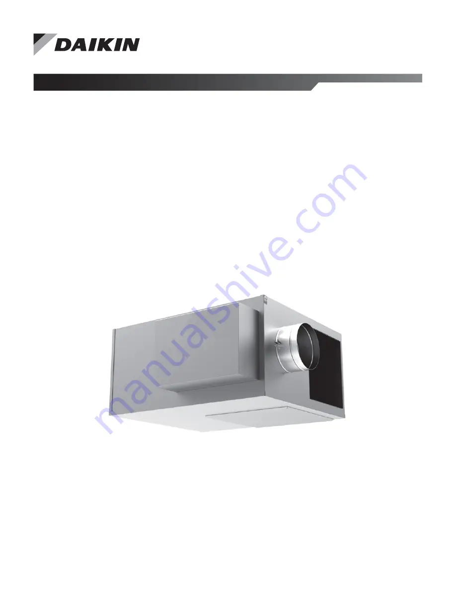
Parallel Fan Powered
Variable Air Volume (VAV)
Terminal Box
Model MQFVI5
Page 1: ...Installation and Maintenance Manual IM 1102 Group Applied Air Systems Part Number IM 1102 Date October 2010 Parallel Fan Powered Variable Air Volume VAV Terminal Box Model MQFVI5 ...
Page 2: ... 4 Connecting Ductwork 6 Minimum Clearance for Access 6 Field Electrical Wiring 6 Fan Powered Air Terminal Units with Electric Heat 6 Fan Powered Air Terminal Units with Hot Water Coils 6 Controls 7 Labeling 7 Flow Sensor 7 Initial Start up Adjustment of Fan Flow Rate 7 Fan Maintenance Procedure 7 Troubleshooting 8 Possible Conditions 8 Investigating Noise Complaints 9 Controls 9 Electric Duct Hea...
Page 3: ... for his or her application The following are trade names or registered trademarks of their respective companies BACnet from the American Society of Heating Refrigerating and Air Conditioning Engineers Inc Windows from Microsoft Corporation Daikin and MicroTech from Daikin Applied Hazardous Information Messages Familiarize yourself with the hazard identification messages used in this manual DANGER...
Page 4: ...e mounted right side up The fan powered unit must be level within or 10 degrees of horizontal both parallel to the air flow and at the right angle of air flow The control side of the terminal is labeled with an arrow indicating UP Unless otherwise noted most analog and digital controls may be installed in any orientation Check with the local Daikin representative for verification CAUTION The equip...
Page 5: ...Installation www DaikinApplied com 5 IM 1102 PARALLEL TERMINAL BOX Figure 1 Hanging straps Figure 2 Trapeze Hangers Figure 3 Optional hanging brackets and hanger rods ...
Page 6: ...ck hazard Can cause personal injury or equipment damage This equipment must be properly grounded Connections and service to the MicroTech III Chiller Unit Controller must be performed only by personnel knowledgeable in the operation of the equipment being controlled All field wiring must comply with the local codes and with the National Electrical Code ANSI NFPA 70 2002 When applicable electrical ...
Page 7: ...pped to California 7 Orientation label identifies the proper air flow direction and the top of the unit Flow Sensor Fan Powered Air Terminals are shipped with a factory installed pressure differential flow sensor installed See Figure 4 for the calibration curve Initial Start up Adjustment of Fan Flow Rate WARNING Solid state speed controls cause all electric motors to run hotter and speed reductio...
Page 8: ...ged intake filter if supplied 4 Re adjust the fan speed control 5 Discharge static pressure too high If repair or replacement of blower or motor is required the motor and fan should be removed as an assembly 1 Disconnect power prior to removal 2 Remove the bottom blower access panel 3 Disconnect the two electrical leads from Terminal Connection 1 and 2 on the motor 4 Remove the bottom two lug scre...
Page 9: ...n concerning controls provided by Daikin For controls provided by others contact the local control representative for assistance Electric Duct Heater WARNING Electric shock hazard Can cause personal injury or equipment damage This equipment must be properly grounded Connections and service to the MicroTech III Chiller Unit Controller must be performed only by personnel knowledgeable in the operati...
Page 10: ...rom the pitot tube located in the control cabinet Attach a magnehelic gauge to the pitot tube Available static pressure at the pitot tube should be 0 03 S P or 0 03 S P If the available static pressure is in the dead band between these two ranges the switch will not engage and some method must be devised to increase the available static pressure If sufficient static pressure is available check to ...
Page 11: ...Troubleshooting www DaikinApplied com 11 IM 1102 PARALLEL TERMINAL BOX Figure 4 MI Flow Sensor Calibration Chart ...
Page 12: ...nt to its standard terms and conditions of sale including Limited Product Warranty Consult your local Daikin Applied representative for warranty details To find your local Daikin Applied representative go to www DaikinApplied com Aftermarket Services To find your local parts office visit www DaikinApplied com or call 800 37PARTS 800 377 2787 To find your local service office visit www DaikinApplie...