background image


Modular-Light AHU


User Manual


3


3.


User Interface: Room Unit 

This section shows the functionalities of the user interface, the Room Unit module, that is used to measure 

room temperature and to manage main control functions of the unit: 

-


Unit state changeover 

-


Cool/Heat mode changeover 

-


Temperature control 

-


Fan speed control 

-


Occupancy mode enabling 

-


Date/time and time scheduler setting 

-


Alarms management 

3.1


Mounting instructions 

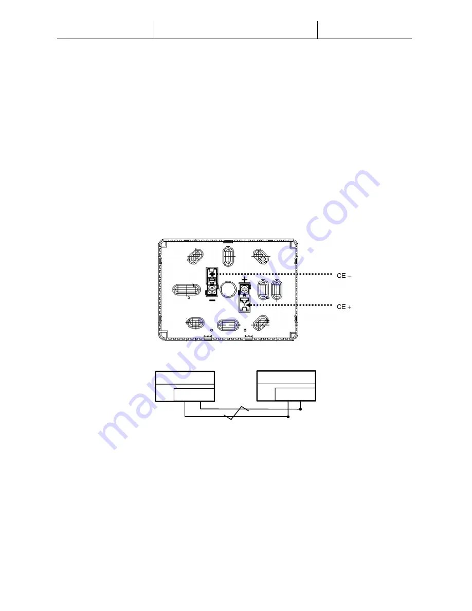
The  Room  Unit  receives  its  power  from  the  connected  controller  via  the  2-wire  interface  (low  voltage, 
SELV). The Room Unit must be connected to the main unit with an unscreened two-core twisted pair cable. 


Following some advices for the correct mounting and operation: 
 
-


The unit should not be mounted in recesses, shelving, behind curtains or doors or above or near direct 
heat sources. 

 
-


Avoid direct sun and draught.  

 
-


The  conduit must  be  sealed  on  the  device  side,  as  currents of  air  in  the  conduit  can  affect  the  sensor 
reading.  

 
-


The admissible ambient conditions must be observed.  

CE-   CE+ 

Unit Controller 

CE-   CE+ 

Room Unit 

Twisted pair 

Summary of Contents for Modular-Light AHU

Page 1: ...User Manual Modular Light AHU ...

Page 2: ...e supply voltage before opening the apparatus cabinet Never work when the power is on Avoid electromagnetic and other interference voltages in signal and connection cables Assembly and installation of system and plant components may only be performed in accordance with corresponding installation instructions and instructions for use Every electric part of the system must be protected against stati...

Page 3: ...ns The Room Unit receives its power from the connected controller via the 2 wire interface low voltage SELV The Room Unit must be connected to the main unit with an unscreened two core twisted pair cable Following some advices for the correct mounting and operation The unit should not be mounted in recesses shelving behind curtains or doors or above or near direct heat sources Avoid direct sun and...

Page 4: ...3 2 Button Overview The Room Unit interface has the following operating elements 1 On Off Unit state changeover 8 Cool Heat Mode Switch between Cooling Summer and Heating Winter mode 2 Home Enabling Disabling of Occupancy mode main page return button 7 Fan Speed Change the supply and return fan speed control mode 3 Program Set date time and time scheduler 6 OK Confirm button and alarm management 4...

Page 5: ...is in On Ventilation or Economy state 2 Off when the unit is Off 3 Blinking when the unit is in Test mode or in off state by Panel Switch Unit control mode set to Auto The actual unit state and relative icons On Off Ventilation or Economy are based on Time Scheduler settings Economy mode active Ventilation mode active Occupancy mode active Dehumidification control active Heating mode Winter Coolin...

Page 6: ...nts 3 Confirm the change of state by pressing for at least 1 second the OK button 4 To return to the main screen page without taking any action either press the Home button or wait for 5 seconds Occupancy mode Occupancy is a function that allows to run the unit for fixed period even if it is Off via time scheduler This time period can be configured during unit commissioning To activate deactivate ...

Page 7: ...tton the hour is saved and minutes blink then set minutes with and 3 By pressing the OK button minutes are saved and the entire time blinks then set the time display format 12 24 hour with or 4 By pressing the OK button the display format is saved and the year blinks then set the desired year with and 5 By pressing the OK button the year is saved and the display shows month day with month blinking...

Page 8: ...es can be set up for each day By setting up the switch the user can set a time point and select one operation in Auto mode To set the time scheduler follow these steps 1 Hold PROG button to enter time scheduler setting In time scheduler button is used to cancel while OK button to confirm 2 Pressing button or the number of corresponding weekday will blink on screen Holding button or cursor will kee...

Page 9: ...n of weekdays pressing or again will jump to the following view The first line is number of operation the second line is time setting the invalid time is used to add a switch 6 Press button and to set up time point and select an operation and press to confirm the input The operation codes are the following 0 Off 1 On 2 Ventilation 3 Economy In any parts of time area press when the cursor is locate...

Page 10: ...m the main setpoint Fan speed control This button allows the user to change actual control mode for Supply and Return fan To change fan speed control mode follow these steps 1 Press Ventilation button 2 Navigate through the different available states by pressing or buttons Auto unit follows nominal fan setpoints Speed 1 unit follows fixed speed 1 value Speed 2 unit follows fixed speed 2 value Spee...

Page 11: ...ollowing meanings FL Fault alarm unit stops OP Operation alarm unit keeps running The other part of the string represents the numeric code of the alarm For a complete list of alarm code check the following table Alarm Code Alarm String Description OP01 Filter alarm Supply or Return filter dirty differential pressure switch of the filters detected an high pressure difference pressure between input ...

Page 12: ...ure out of the allowable range or error condition on the pressure sensor not connected or broken FL16 Return fan sensor fault Return fan pressure sensor error measured pressure out of the allowable range or error condition on the pressure sensor not connected or broken The present publication is drawn up by of information only and does not constitute an offer binding upon Daikin Applied Europe S p...

Reviews: