Download and Configuration
OM 1085-6 • MICROTECH III CONTROLLER
Downloading to Baseboard #668105601 or I/O Expansion Module #668105702 with
Segger Flasher5 Programmer
The following section describes how to download the unit
controller baseboard or I/O expansion module using the
Flasher5 (legacy) programming tool.
Getting Started
You will need the following:
•
WSHP unit controller baseboard with hardware part
number 668105601 or I/O expansion board with hardware
part number 668105702.
• Segger Flasher5 programmer hardware and software.
• Computer with Windows-compatible
operating system.
Refer to
• WSHP unit controller or I/O expansion module “.hex”
file saved to your hard drive. Contact the ATS Technical
Support Team at 315-282-6434 to request a copy of this
software file.
Installing Segger Flasher5 Software
If the software has not been previously installed and
configured, follow steps 1-5 below. Otherwise, skip to step 1 of
the next section:
1. Download the most recent version of Flasher5 software
www.segger.com/downloads/flasher.
2. Save the application to your hard drive.
3. Open the SetupFlasher application; click Next from the
Welcome screen.
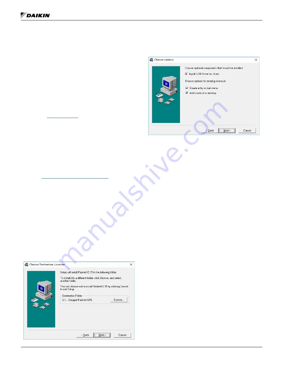
4. Click Next from the Choose Destination Location screen
(
) to choose the default hard drive location.
5. Check all three boxes for available options as shown in
Figure 23 and click Next.
NOTE:
The JTAG hardware and software tools referenced
here are manufactured by Segger Microcontroller
Systems. However, there are other manufacturers of
JTAG-supported programming tools that would also
be acceptable.
Figure 22:
Choose Destination
Figure 23: Choose Options
Once the Flasher software has been installed, follow the
steps below to download the unit controller and I/O expansion
module. The unit controller and I/O expansion module have
different software files and must be downloaded separately.
NOTE:
New unit controller software may be installed over
an existing version. It is not necessary to uninstall
software prior to loading a newer version.
1. Refer to
o verify the latest version of
software.
2. Remove power to the unit controller and the BACnet or
LonWorks
communication module (if attached).
3. Download the unit controller software, which is a “.hex”
file type and save to the hard drive. To request a copy of
the software file, contact the ATS Technical Response
Team at 315-282-6434.
4. Connect the Flasher5 hardware between the serial port
on the computer (or a USB to serial converter) and the
10-pin connector on the unit controller or I/O expansion
module. The Pin1 triangle on the Flasher cable (brown
wire) must line up with the Pin1 triangle on the board.
5. Connect power to the Flasher5 hardware.
6. If a room or return air sensor connected to TB1 or H9 on
the unit controller, and jumper JP6 is shorted, remove
this jumper.
7. If a thermostat is connected to TB2 on the unit controller
and jumper JP6 is not shorted, short-jumper JP6 to
prevent the unit from running during the download
process.
8. Switch the Programming Jumper from the RUN position
to the PRG position on the board being downloaded (unit
controller baseboard or I/O expansion module) as shown
in
9. If there is an I/O expansion module connected to the unit
Summary of Contents for MicroTech III
Page 39: ......


