


s
eleCTed
p
arameTers
I
nformaTIon
www.DaikinApplied.com 47
ED 15103-6 • MICROTECH III WSHP UNIT CONTROLLER
s
eleCTed
p
arameTers
I
nformaTIon
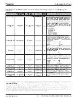
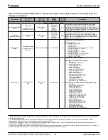
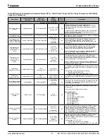
The following section provides greater detail for the Binary
Input Status and Binary Output parameters noted in the
summary tables.
Binary Input Status
Table 21:
Binary Input Status Bit Descriptions - Enfinity Single Stage Compressor (Models MHC/MHW, CCH/CCW, VFC/
VFW, LVC/LVW, VHC/VHF)
Bit Number
Bit Description
Setting
Description
Unit Controller Jumpers
0
Normal/Test Mode
Jumper 1 = Open (0)
Normal operation
Jumper 1 = Shorted (1)
Service/Test mode operation
1
Fan Operation
(Jumper applies to unit controller v3.1 and
newer and also for v3.0 and older using room
sensor control without a fan On/Auto switch)
Jumper 2 = Open (0)
Continuous fan operation
Jumper 2 = Shorted (1)
Cycling fan operation
2
Loop Fluid
Jumper 3 = Open (0)
Water loop fluid
Jumper 3 = Shorted (1)
Glycol loop fluid
3
Alarm ‘A’ Terminal Polarity Select
(Unit controller v3.1 and newer)
Jumper 4 = Open (0)
Fault de-energizes alarm output to 0VAC
Jumper 4 = Shorted (1)
Fault energizes alarm output to 24VAC
4
Room Sensor Setpoint Adjust Range
Jumper 5 = Open (0)
Short range: -3º to +3º F (-1.67º to +1.67º C)
Jumper 5 = Shorted (1)
Long range: 55º to 95º F (12.78º to 35ºC)
5
Thermostat/Room Sensor
Jumper 6 = Open (0)
Thermostat control
Jumper 6 = Shorted (1)
Room sensor control
6
Not used
Jumper 7 = Open (0)
7
Not used
Jumper 8 = Open (0)
Unit Controller Inputs
8
Compressor #1 Low Pressure Switch
Switch Closed (1)
Low Pressure Switch for compressor #1 is normal
Switch Open (0)
Low Pressure Switch for compressor #1 is in alarm
9
Compressor #1 High Pressure Switch
Switch Closed (1)
High Pressure Switch for compressor #1 is normal
Switch Open (0)
High Pressure Switch for compressor #1 is in alarm
10
Emergency Shutdown
Open (0)
Unit shuts down
11
Local Occupancy Switch
Switch Open (0)
Unoccupied
1
Switch Closed (1)
Occupied
12
Thermostat Timed Override
(O – Terminal)
Switch Closed (1)
If the Timed Override switch is pressed for more than 3 seconds
but less than 10 seconds while in the Unoccupied mode, the
unit goes into the Timed Override mode (the thermostat has a
pushbutton for Timed Override)
13
Thermostat Fan Request
(G – Terminal)
Switch Closed (1)
Thermostat fan operation is requested
14
Thermostat Cool Stage #1
(Y1 – Terminal)
Switch Closed (1)
First stage of thermostat cooling is requested
15
Thermostat Cool Stage #2
(Y2 – Terminal)
Switch Closed (1)
Second stage of thermostat cooling is requested
16
Thermostat Heat Stage #1
(W1 – Terminal)
Switch Closed (1)
First stage of thermostat heating is requested
17
Thermostat Heat Stage #2
(W2 – Terminal)
Switch Closed (1)
Second stage of thermostat heating is requested
I/O Expansion Module Jumpers
18
Number of Compressors
Jumper 1 = Open (0)
Single compressor
Jumper 1 = Shorted (1)
Dual compressor
19
Hot Gas/Water Reheat (HGR)
Jumper 2 = Open (0)
None
Jumper 2 = Shorted (1)
Hot Gas/Water Reheat (HGR)
20 & 21
Secondary Heating Options
(2 Jumpers)
Jumper 3 = Open (0)
None
Jumper 4 = Open (0)
Jumper 3 = Shorted (1)
Supplemental electric heat
Jumper 4 = Open (0)
Jumper 3 = Open (0)
Boilerless electric heat
Jumper 4 = Shorted (1)
1. This switch is effective only when the network scheduling is not in use.


