Installation Manual 3P291714-2B
DCM601A71 intelligent Touch Manager
11
English
1.3.2
Front panel
Located below the monitor display on the front panel are four LEDs that indicate the oper-
ating status of the intelligent Touch Manager. Sliding the front slide cover down and then
removing a screwed cover reveals terminals used during the setup after installation or
during maintenance work.
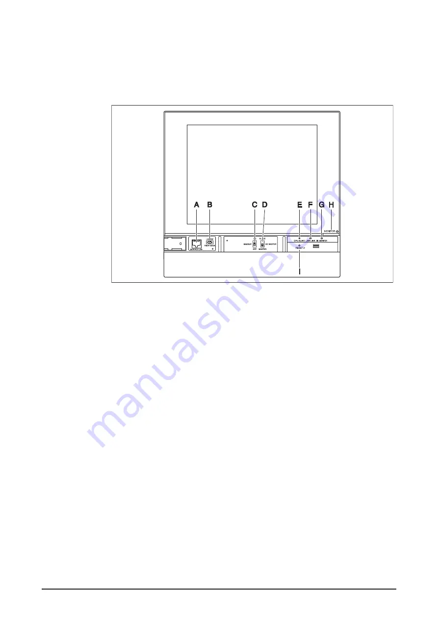
<Front face of intelligent Touch Manager>
A [SERVICE LAN]
The port for temporarily connecting the intelligent Touch Manager
to a LAN from its front face, instead of its rear face, during the operations such as
installation or maintenance.
B [LAN SW]
This is for switching between the LAN port on the back and the SERVICE
LAN port on the front.
You cannot close the cover when the switch set to “FRONT”. To close the cover, select
“BACK”.
C [BACKUP]
The switch for turning on/off the backup power supply for retaining the
current settings.
D [DIII MASTER]
The switch for setting “MASTER” or “SLAVE” when there are multiple
DIII-NET centralized controllers such as intelligent Touch Manager.
E [CPU ALIVE]
LED (Green) The LED that indicates that the CPU is operating nor-
mally. The CPU is operating normally when this LED is blinking and malfunctioning
when it is on or off.
(It takes about 10 seconds for detection of the abnormality.)
On: Software error
Off: Hardware error or power off
F [LAN LINK]
LED (Green) The LED that indicates whether or not the hardware con-
nection is established normally between the intelligent Touch Manager and the equip-
ment connected to the LAN port. It is lit when there is no error.
G [DIII MONITOR]
LED (Yellow) This LED blinks when data is sent or received via DIII-
NET communication line.
H [MONITOR]
key and LED (Orange/Green) Each time you press this key, the monitor
display turns on/off. The color of the LED also changes simultaneously.
Off: The monitor is powered off.
On (Orange): The monitor display is off.
On (Green): The monitor display is on.
I
[RESET//]
The switch for restarting the intelligent Touch Manager.
Summary of Contents for intelligent Touch Manager
Page 1: ...intelligent Touch Manager Model DCM601A71 Installation Manual 3P291714 2B...
Page 42: ......
Page 43: ......
Page 44: ...3P291714 2B EM11A018A 1306 HT...


