


DAIKIN
ILINQ
QUICK START GUIDE
9
Pressing the ENTER button on a weekday or holiday event screen selects the Event1 Start
Hour. The UP and DOWN buttons can be used to modify the value. Pressing ENTER accepts
the new value and selects the Event1 Start Minute. The UP and DOWN buttons can be used to
modify the value. Pressing ENTER accepts the new value and selects the Event1 AM/PM
designation. Use the UP or DOWN button to toggle the value and press ENTER to accept. This
process is repeated for the start and stop time settings for the four events. Additional
information on time schedule settings is provided in the Daikin
iLINQ
User Manual.
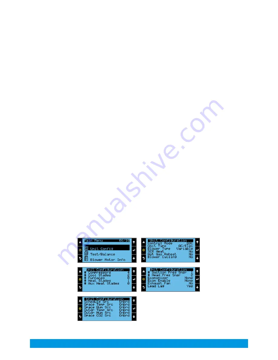
Unit Configuration Settings
Select the Unit Configuration option from the Main Menu to verify that the unit configurations
are correct. Many of these settings are set at the factory to match the unit where the controller
is installed but should be confirmed, and others are determined by site preferences or field-
installed options. Additional information on unit configuration settings is provided in the Daikin
iLINQ
User Manual.
•
Changing the Control Mode from DDC to TSTAT configures the controller to accept
commands from a traditional thermostat instead of using the DDC controller application
logic. Follow wiring modification steps outlined in the Daikin
iLINQ
User Manual.
•
Setting Blower Cycling to Yes allows the main blower to be cycled off during occupied
hours when there is no need for cooling or heating for applications where continuous
fresh air ventilation is not required.
•
If an economizer option has been installed on the unit, verify that the Economizer
setting
has been set to Installed or Installed With CO2 as needed.
•
Setting the Sensor Source selection of a sensor to Network causes the controller to use
the sensor value from the LonWorks
®
or BACnet
®
communication interface instead of
the onboard wiring connections.
•
Change the Schedule Source from Onboard to Remote if the Remote Start Stop input is
to be used for occupancy instead of the defined time schedule. Set to Force Occupied
or
Force Unoccupied to bypass scheduling.


