background image

EDUS391300-F9

Installation

FXZQ-MVJU9

45

C: 3P184443-12N

23

3P184443-12N

English

9-3 

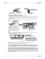
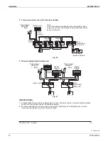
CONTROL BY 2 REMOTE CONTROLLERS (CONTROLLING 1 INDOOR UNIT BY 2 
REMOTE CONTROLLERS)

r

When using 2 remote controllers, one must be set to 

MAIN

 and the other to 

SUB

.

Wiring Method 

5GG

8. ELECTRIC WIRING WORK

)

(1) 

4GOQXGVJGEQPVTQNDQZEQXGT

(2) 

#FFTGOQVGEQPVTQNNGTVQVJGVGTOKPCNDNQEMHQTTGOQVGEQPVTQNNGT2

1

, P

2

KPVJGEQPVTQNDQZ6JGTGKU

PQRQNCTKV[4GHGTVQ

(KI

 and 

Table 8-3

)

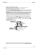
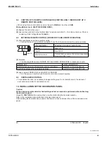
EXTERNAL REMOTE CONTROL (FORCED OFF AND ON/OFF OPERATION)

(1) 

9KTGURGEKƂECVKQPUCPFJQYVQRGTHQTOYKTKPI

r

Connect the input from outside to terminals T1 and T2 of the terminal block for remote controller.

Input A

FORCED 
OFF

T2

T1

F2

9KTGURGEKƂECVKQP

5JGCVJGFXKP[NYKTKPIQTECDNGYKTG

Gauge

AWG 18-16

Length

/CZHV

'ZVGTPCNVGTOKPCN

Contact that can ensure the minimum applicable 
load of 15V DC, 1 mA.

(2) 

Actuation

r 6JGHQNNQYKPIVCDNGGZRNCKPU(14%'&1((CPF101((12'4#6+105KPTGURQPUGVQKPRWV#

FORCED OFF

ON/OFF OPERATION

+PRWV10UVQRUQRGTCVKQPKORQUUKDNGD[TGOQVGEQPVTQNNGTU

Input OFF 

Æ

 ON turns ON unit.

Input OFF enables control by remote controller

Input ON 

Æ

 OFF turns OFF unit.

(3) 

How to select FORCED OFF and ON/OFF OPERATION

r

Turn the power on and then use the remote controller to select operation.

9-5 CENTRALIZED 

CONTROL

r

For centralized control, it is necessary to designate the group No. For details, refer to the manual of 
each optional controller for centralized control.

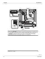
INSTALLATION OF THE DECORATION PANEL

Caution:

9KVJCYKTGNGUUTGOQVGEQPVTQNNGTƂGNFUGVVKPICPFVGUVTWPECPPQVDGRGTHQTOGFYKVJQWVCVVCEJKPI

the decoration panel.

<Read 

12. TEST  RUN

 before making a test run without attaching the decorated panels.>

Refer to the installation manual attached to the decoration panel.
After installing the decoration panel, ensure that there is no space between the unit body and decoration 
panel.

Summary of Contents for FXZQ-MVJU9

Page 1: ...EDUS391300 F9 FXZQ MVJU9 4 Way Ceiling Mounted Cassette Unit 2 2 ...

Page 2: ......

Page 3: ...stics 8 6 Safety Devices Setting 9 7 Capacity Tables 10 7 1 Cooling Capacity 10 7 2 Heating Capacity 11 8 Air Velocity and Temperature Distributions Reference Data 12 9 Sound Levels Reference 20 9 1 Overall 20 9 2 Octave Band Level 20 10 Center of Gravity 22 11 Installation 23 12 Accessories 48 12 1 Optional Accessories For Unit 48 12 2 Optional Accessories For Controls 48 ...

Page 4: ...g thermal insulation material Foamed polystyrene Foamed polystyrene Foamed polystyrene Machine Weight Mass Lbs kg 42 19 42 19 42 19 Piping Connections Liquid Pipes in mm φ1 4 6 4 Flare Connection φ1 4 6 4 Flare Connection φ1 4 6 4 Flare Connection Gas Pipes in mm φ1 2 12 7 Flare Connection φ1 2 12 7 Flare Connection φ1 2 12 7 Flare Connection Drain Pipe in mm VP20 External Dia 1 1 32 26 Internal D...

Page 5: ... Drive Direct Drive Temperature Control Microprocessor Thermostat for Cooling and Heating Microprocessor Thermostat for Cooling and Heating Sound absorbing thermal insulation material Foamed polystyrene Foamed polystyrene Machine Weight Mass Lbs kg 42 19 42 19 Piping Connections Liquid Pipes in mm φ1 4 6 4 Flare Connection φ1 4 6 4 Flare Connection Gas Pipes in mm φ1 2 12 7 Flare Connection φ1 2 1...

Page 6: ...Dimensions EDUS391300 F9 4 FXZQ MVJU9 2 Dimensions FXZQ07MVJU9 FXZQ09MVJU9 FXZQ12MVJU9 FXZQ15MVJU9 FXZQ18MVJU9 C 3D080462 ...

Page 7: ...EDUS391300 F9 Dimensions FXZQ MVJU9 5 FXZQ07MVJU9 FXZQ09MVJU9 FXZQ12MVJU9 FXZQ15MVJU9 FXZQ18MVJU9 BYFQ60B8W1U 3D080470 ...

Page 8: ...Piping Diagrams EDUS391300 F9 6 FXZQ MVJU9 3 Piping Diagrams Unit in mm Capacity GAS Liquid FXZQ07MVJU9 FXZQ09MVJU9 FXZQ12MVJU9 FXZQ15MVJU9 FXZQ18MVJU9 φ1 2 12 7 φ1 4 6 4 4D040157B ...

Page 9: ...EDUS391300 F9 Wiring Diagrams FXZQ MVJU9 7 4 Wiring Diagrams FXZQ07MVJU9 FXZQ09MVJU9 FXZQ12MVJU9 FXZQ15MVJU9 FXZQ18MVJU9 C 3D080350A ...

Page 10: ...Electric Characteristics EDUS391300 F9 8 FXZQ MVJU9 5 Electric Characteristics 4D080464 ...

Page 11: ...ty Devices Setting FXZQ MVJU9 9 6 Safety Devices Setting 3D080474A Safety devices 07 09 12 15 18 FXZQ MVJU9 PC board fuse 250V 5A Fan motor thermal fuse F Fan motor thermal protector F C OFF 266 9 130 5 ON 181 4 36 83 20 ...

Page 12: ...5 7 12 75 9 5 6 9 10 7 7 5 12 0 8 0 13 3 8 4 13 5 7 9 13 7 7 6 79 9 5 6 9 10 7 7 5 12 0 8 0 13 1 8 3 13 3 7 9 13 5 7 5 83 9 5 6 9 10 7 7 5 12 0 8 0 12 9 8 2 13 0 7 8 13 3 7 4 87 9 5 6 9 10 7 7 5 12 0 8 0 12 7 8 1 12 8 7 7 13 1 7 3 91 9 5 6 9 10 7 7 5 12 0 8 0 12 5 7 9 12 6 7 6 12 8 7 2 95 9 5 6 9 10 7 7 5 12 0 8 0 12 2 7 8 12 4 7 5 12 6 7 1 99 9 5 6 9 10 7 7 5 11 8 7 9 12 0 7 7 12 2 7 4 12 4 7 0 1...

Page 13: ...10 7 10 1 12 22 0 20 0 12 4 12 4 12 4 12 4 12 4 12 3 26 0 24 0 13 2 13 1 13 1 13 1 13 1 12 7 30 0 28 0 13 9 13 9 13 9 13 9 13 5 12 7 35 0 32 0 14 8 14 7 14 5 14 0 13 5 12 7 39 0 36 0 15 6 15 3 14 5 14 0 13 5 12 7 44 0 40 0 16 3 15 3 14 5 14 0 13 5 12 7 47 0 43 0 16 3 15 3 14 5 14 0 13 5 12 7 51 0 47 0 16 3 15 3 14 5 14 0 13 5 12 7 54 0 50 0 16 3 15 3 14 5 14 0 13 5 12 7 57 0 53 0 16 3 15 3 14 5 14...

Page 14: ...Air Velocity and Temperature Distributions Reference Data EDUS391300 F9 12 FXZQ MVJU9 8 Air Velocity and Temperature Distributions Reference Data FXZQ07 09MVJU9 Cooling mode C 4D080700 ...

Page 15: ...EDUS391300 F9 Air Velocity and Temperature Distributions Reference Data FXZQ MVJU9 13 FXZQ07 09MVJU9 Heating mode C 4D080701 ...

Page 16: ...Air Velocity and Temperature Distributions Reference Data EDUS391300 F9 14 FXZQ MVJU9 FXZQ12MVJU9 Cooling mode C 4D080709 ...

Page 17: ...EDUS391300 F9 Air Velocity and Temperature Distributions Reference Data FXZQ MVJU9 15 FXZQ12MVJU9 Heating mode C 4D080710 ...

Page 18: ...Air Velocity and Temperature Distributions Reference Data EDUS391300 F9 16 FXZQ MVJU9 FXZQ15MVJU9 Cooling mode C 4D080711 ...

Page 19: ...EDUS391300 F9 Air Velocity and Temperature Distributions Reference Data FXZQ MVJU9 17 FXZQ15MVJU9 Heating mode C 4D080712 ...

Page 20: ...Air Velocity and Temperature Distributions Reference Data EDUS391300 F9 18 FXZQ MVJU9 FXZQ18MVJU9 Cooling mode C 4D080713 ...

Page 21: ...EDUS391300 F9 Air Velocity and Temperature Distributions Reference Data FXZQ MVJU9 19 FXZQ18MVJU9 Heating mode C 4D080714 ...

Page 22: ...208 230V 60Hz 2 The operating values were obtained in an anechoic chamber conversion values 3 Sound levels will vary depending on a range of factors such as the construction acoustic absorption coefficient of the particular room in which the equipment is installed dB A Model 208 230V 60Hz H L FXZQ07MVJU9 32 29 FXZQ09MVJU9 32 29 FXZQ12MVJU9 33 29 FXZQ15MVJU9 36 30 FXZQ18MVJU9 41 34 FXZQ07MVJU9 FXZQ...

Page 23: ...EDUS391300 F9 Sound Levels Reference FXZQ MVJU9 21 FXZQ15MVJU9 FXZQ18MVJU9 4D080467 4D080468 ...

Page 24: ...Center of Gravity EDUS391300 F9 22 FXZQ MVJU9 10 Center of Gravity FXZQ07MVJU9 FXZQ09MVJU9 FXZQ12MVJU9 FXZQ15MVJU9 FXZQ18MVJU9 4D080472 ...

Page 25: ...lways use a licensed installer or contractor to install this product Improper installation can result in YCVGT QT TGHTKIGTCPV NGCMCIG GNGEVTKECN UJQEM ƂTG QT GZRNQUKQP Meanings of DANGER WARNING CAUTION and NOTE Symbols DANGER Indicates an imminently hazardous situation which if not avoided will result in death or serious injury WARNING Indicates a potentially hazardous situation which if not avoi...

Page 26: ...PI CPF causing injuries r Take into account strong winds typhoons or earthquakes when installing Improper installation could result in the unit falling and causing accidents r Make sure that a separate power supply circuit is provided for this unit and that all electrical YQTM KU ECTTKGF QWV D SWCNKƂGF RGTUQPPGN CEEQTFKPI VQ NQECN UVCVG CPF PCVKQPCN TGIWNCVKQPU P KPUWHƂEKGPV RQYGT UWRRN ECRCEKV QT...

Page 27: ...ness of the refrigerant piping installation Read the chapter Refrigerant Piping WORK and follow the procedures r 5KPEG 4 KU C DNGPF VJG TGSWKTGF CFFKVKQPCN TGHTKIGTCPV OWUV DG EJCTIGF KP KVU NKSWKF UVCVG If the refrigerant is charged in a state of gas its composition can change and the system will not work properly r 6JG KPFQQT WPKV KU HQT 4 5GG VJG ECVCNQI HQT KPFQQT OQFGNU VJCV ECP DG EQPPGEVGF ...

Page 28: ...nit or moving it after opening be sure to lift it by holding on to the hanger brackets YKVJQWV GZGTVKPI CP RTGUUWTG QP QVJGT RCTVU GURGEKCNN FTCKP RKRKPI CPF QVJGT TGUKP RCTVU r Decide upon a line of transport r Leave the unit inside its packaging while moving until reaching the installation site Use a sling of soft material where unpacking is unavoidable or protective plates together with a sling...

Page 29: ...antity 4 pcs 1 each 1 each 2 pcs 1pc 2pcs Shape QT ICU RKRG QT NKSWKF RKRG CTIG 5OCNN 2 3 OPTIONAL ACCESSORIES r 6JG QRVKQPCN FGEQTCVKQP RCPGN CPF TGOQVG EQPVTQNNGT CTG TGSWKTGF HQT VJKU KPFQQT WPKV 4GHGT VQ Table 1 and 2 Table 1 Model Optional decoration panel FXZQ07 09 12 15 18MVJU9 BYFQ60B8W1U Color White r These are two types of remote controllers wired and wireless Select a remote controller ...

Page 30: ...IG PQVGF The refrigerant charge in the system is not clear b Items to be checked at time of delivery Also review the SAFETY CONSIDERATIONS Items to be checked Check TG VJG EQPVTQN DQZ EQXGT CKT ƂNVGT CPF UWEVKQP ITKNNG CVVCEJGF KF QW GZRNCKP CDQWV QRGTCVKQPU YJKNG UJQYKPI VJG QRGTCVKQP OCPWCN VQ QWT EWUVQOGT KF QW JCPF VJG QRGTCVKQP OCPWCN QXGT VQ QWT EWUVQOGT c Points for explanation about operat...

Page 31: ... units and the power supply wiring and remote controller wiring must be installed at least 40 in away from any televisions or radios This is to prevent interference with picture CPF UQWPF TGEGRVKQP PVGTHGTGPEG OC QEEWT GXGP CV KP CYC FGRGPFKPI QP VJG TGEGRVKQP SWCNKV r If installing the wireless kit the distance of the signal sent from the remote controller might be shorter if VJGTG CTG ƃWQTGUEGPV...

Page 32: ...ew as seen from A Hanger bracket False ceiling KP Fig 3 KI NOTE r Installation is possible with a ceiling FKOGPUKQP QH KP OCTMGF YKVJ However to achieve a ceiling panel QXGTNCRRKPI FKOGPUKQP QH KP VJG spacing between the ceiling and the unit UJQWNF DG KP QT NGUU H VJG URCEKPI between ceiling and the unit is over KP CVVCEJ EGKNKPI OCVGTKCN VQ part or recover the ceiling 1 3 4 1 3 4 False ceiling Fa...

Page 33: ...and branch duct before installing the unit U HQT VJG RCTVU VQ DG WUGF HQT KPUVCNNCVKQP YQTM DG UWTG VQ WUG VJG RTQXKFGF CEEGUUQTKGU CPF URGEKƂGF parts designated by Daikin 1 For new ceilings 1 1 Install the indoor unit temporarily r VVCEJ VJG JCPIGT DTCEMGV VQ VJG UWURGPUKQP DQNV G UWTG VQ ƂZ KV UGEWTGN D WUKPI C PWV CPF YCUJGT HTQO VJG WRRGT CPF NQYGT UKFGU QH VJG JCPIGT DTCEMGV 6JG YCUJGT ƂZKPI ...

Page 34: ...PUV EQPFGPUCVG ƃQY VJG ƃQCV UYKVEJ OC OCNHWPEVKQP CPF ECWUG YCVGT VQ FTKR 1 5 4GOQXG VJG YCUJGT ƂZKPI RNCVG WUGF HQT RTGXGPVKPI VJG YCUJGT HTQO HCNNKPI CPF VKIJVGP VJG upper nut 1 6 4GOQXG VJG RCRGT RCVVGTP HQT KPUVCNNCVKQP 2 For existing ceilings 2 1 Install the indoor unit temporarily r VVCEJ VJG JCPIGT DTCEMGV VQ VJG UWURGPUKQP DQNV G UWTG VQ ƂZ KV UGEWTGN D WUKPI C PWV CPF YCUJGT HTQO VJG WRRG...

Page 35: ...ant to get mixed into the refrigerant circuit such as air If any refrigerant gas leaks while working on the unit thoroughly ventilate the room immediately r Q PQV OKZ CKT QT QVJGT ICU YKVJ VJG URGEKƂGF TGHTKIGTCPV KP VJG refrigeration circuit r Ventilate the room if refrigerant gas leaks during the work r The outdoor unit is charged with refrigerant r Be sure to use both a spanner and torque wrenc...

Page 36: ...VKEWNCT KH VJG ƃWZ EQPVCKPU ƃWQTKPG KV YKNN FCOCIG VJG refrigerant oil r GHQTG DTC KPI ƂGNF TGHTKIGTCPV RKRKPI PKVTQIGP ICU UJCNN DG DNQYP VJTQWIJ VJG RKRKPI VQ GZRGN CKT HTQO the piping H DTC KPI KU FQPG YKVJQWV PKVTQIGP ICU DNQYKPI C NCTIG COQWPV QH QZKFG ƂNO FGXGNQRU KPUKFG VJG RKRKPI and could cause system malfunction r When brazing the refrigerant piping only begin brazing after having carrie...

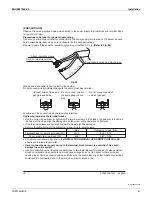
Page 37: ...ain pipe short and sloping downwards at a gradient of at least 1 100 to prevent air pockets from forming r H VJG FTCKP JQUG ECPPQV DG UWHƂEKGPVN UGV QP C UNQRG TGHGT VQ 24 76 105 14 4 0 4 5 0 PIPING on page 14 r To keep the drain hose from sagging space hanger bracket every 40 to 60 in 1 100 gradient or more Hanger bracket GOOD s KP WRONG WRONG Fig 17 Fig 18 CAUTION Water pooling in the drainage p...

Page 38: ... Raising section CEEGUUQT WPKV KP Ceiling slab Level or tilted slightly up CEEGUUQT Fig 21 Ű KP 40 60 in NOTE r 6Q GPUWTG PQ GZEGUUKXG RTGUUWTG KU CRRNKGF VQ VJG KPENWFGF FTCKP JQUG FQ PQV DGPF QT VYKUV VJG hose when installing as it could cause leakage r If converging multiple drain pipes install according to the procedure shown below 21 7 16 in The drain pipe should have a downward slope of at l...

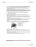
Page 39: ... ECTT KPI QWV YKTKPI YQTM CTQWPF VJG EQPVTQN DQZ OCMG UWTG PQPG QH VJG EQPPGEVQTU EQOG WPFQPG G UWTG VQ CVVCEJ VJG EQPVTQN DQZ EQXGT DGHQTG VWTPKPI QP VJG power 0GZV RTGUU VJG KPURGEVKQP VGUV TWP DWVVQP p on the remote controller The unit will engage the test TWP OQFG 2TGUU VJG QRGTCVKQP OQFG UGNGEVQT DWVVQP p q WPVKN UGNGEVKPI 0 12 4 6 10 p 6JGP RTGUU VJG 10 1 DWVVQP p q 6JG KPFQQT WPKV HCP CPF F...

Page 40: ...e controller wiring Power supply terminal block Ground Single phase power supply 60 Hz 208 230V REMOTE CONTROL TRANSMISSION WIRING FORCED OFF KI CAUTION r Drain piping connections r Do not connect the drain piping directly to sewage pipes that smell of ammonia The ammonia in the sewage might enter the indoor unit through the drain pipes and corrode the heat exchanger r Keep in mind that the drain ...

Page 41: ...r and switch and wiring instructions r Be sure to ground the air conditioner r Do not connect the ground wire to gas and water pipes lightning rods or telephone ground wires r CU RKRGU OKIJV ECWUG GZRNQUKQPU QT ƂTG KH ICU NGCMU r Water pipes no grounding effect if hard vinyl piping is used r Telephone ground wires or lightning rods might cause abnormally high electric potential in the ground durin...

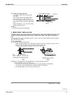
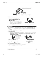
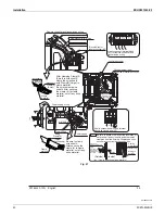
Page 42: ... YKTGU DGVYGGP VJG ENCOR CPF RQYGT UWRRN VGTOKPCN DNQEM 7UG KI CU a guide and allow at least 3 1 4 in for removing the sheath r After connection attach the sealing material Refer to Fig 25 Be sure to attach it to prevent KPƂNVTCVKQP QH YCVGT HTQO VJG QWVUKFG CMG UWTG VJCV VJG UNKV KP VJG UGCNKPI OCVGTKCN KU RQUKVKQPGF vertically HVGT CVVCEJKPI VJG UGCNKPI UETGY VJG EQPFWKV OQWPVKPI RNCVG WUKPI VJG...

Page 43: ...nection may deteriorate protection Tightening torque for the terminal blocks r Use the correct screwdriver for tightening the terminal screws If the blade of screwdriver is too small the head of the screw might be damaged and the screw will not be properly tightened r If the terminal screws are tightened too hard screws might be damaged r Refer to the table below for the tightening torque of the t...

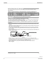
Page 44: ...C OCVGTKCN Remote controller wiring Transmission wiring EQPVTQN DQZ EQXGT Remote controller and transmission wiring GZ QY VQ CVVCEJ UGCNKPI OCVGTKCNU CEEGUUQT REMOTE CONTROL TRANSMISSION WIRING FORCED OFF CEEGUUQT NCOR NCOR CTIG 5OCNN Clamp material Power supply terminal block CEEGUUQT 5GCNKPI OCVGTKCN Attach completely to hole of wiring without leaving any space Sealing OCVGTKCN Wiring to outside...

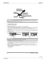
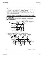
Page 45: ...QNVCIG YKTKPI ITQWPF CPF QVJGT RQYGT YKTKPI CV NGCUV KP UQ VJCV VJG FQ PQV RCUU VJTQWIJ VJG UCOG RNCEG VQIGVJGT 2TQZKOKV OC ECWUG GNGEVTKECN KPVGTHGTGPEG OCNHWPEVKQPU CPF DTGCMCIG 9 2 WIRING EXAMPLE r Fit the power supply wiring of each unit with a switch and breaker fuse as shown in the drawing COMPLETE SYSTEM EXAMPLE Power supply Indoor unit Remote controller Branch Selector unit 1PN HQT GCV rec...

Page 46: ...remote controllers Outdoor unit QPVTQN DQZ KI 3 When including Branch Selector unit F1 F2 F1 F2 F1 F2 F1 F2 P1 P2 P1 P2 F1 F2 T1 T2 F1 F2 F1 F2 P1 P2 P1 P2 F1 F2 T1 T2 L1 L2 L1 L2 L1 L2 L1 L2 IN D OUT D IN D OUT D IN D OUT D Power supply 208 230V 1 60Hz Power supply 208 230V 1 60Hz No 3 System Indoor unit A Most downstream Indoor unit Outdoor unit Branch Selector unit Branch Selector unit QPVTQN D...

Page 47: ...licable load of 15V DC 1 mA 2 Actuation r 6JG HQNNQYKPI VCDNG GZRNCKPU 14 1 CPF 10 1 12 4 6 105 KP TGURQPUG VQ KPRWV FORCED OFF ON OFF OPERATION PRWV 10 UVQRU QRGTCVKQP KORQUUKDNG D TGOQVG EQPVTQNNGTU Input OFF Æ ON turns ON unit Input OFF enables control by remote controller Input ON Æ OFF turns OFF unit 3 How to select FORCED OFF and ON OFF OPERATION r Turn the power on and then use the remote c...

Page 48: ...CTGPVJGUGU Mode 10 Field settings 0 01 4 8 Return Setting FIELD SET MODE MODE NO SECOND CODE NO FIRST CODE NO Fig 32 11 1 SETTING AIR OUTLET DIRECTION r See the installation manual included with the sealing material of air discharge outlet kit sold separately and technical guide for ceiling height settings for two and three direction air discharge 6JG 5 10 1 01 KU HCEVQT UGV VQ CNN TQWPF QWVNGV DG...

Page 49: ...isplayed there may be a problem with the wiring or power so check the wiring again Table 5 Remote control display Content p 064 10641 q KU NKV WR r 6JGTG KU C UJQTV EKTEWKV CV VJG 14 1 VGTOKPCNU 6 6 U4 is lit up UH is lit up r The power on the outdoor unit is off r The outdoor unit has not been wired for power supply r Incorrect wiring for the transmission wiring and or FORCED OFF wiring No displa...

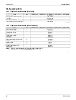
Page 50: ...spacer KDBQ44BA60A Replacement long life filter KAFQ441BA60 Fresh air intake kit Direct installation type KDDQ44XA60 Option Note FXZQ07MVJU9 FXZQ09MVJU9 FXZQ12MVJU9 FXZQ15MVJU9 FXZQ18MVJU9 Remote controller wired 1 BRC1E71 72 Remote controller wireless BRC7E830 Central remote controller DCS302C71 Electrical box KJB311AA Unified ON OFF controller DCS301C71 Electrical box KJB212AA Schedule timer DST...

Page 51: ......
Page 52: ...or explosion Use only those parts and accessories supplied or specified by Daikin Ask a qualified installer or contractor to install those parts and accessories Use of unauthorised parts and accessories or improper installation of parts and accessories can result in water or refrigerant leakage electrical shock fire or explosion Read the User s Manual carefully before using this product The User s...

Reviews: