13 Piping installation
Installation and operation manual
17
FXFA20~125A2VEB
VRV system air conditioner
3P599604-1C – 2020.10
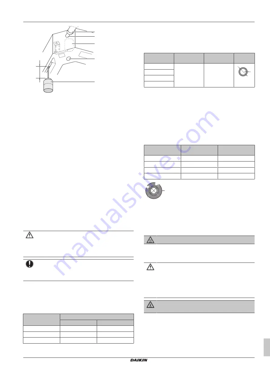
≥100 mm
e
d
c
b
a
a
Plastic watering can
b
Service drain outlet (with rubber plug). Use this outlet to
drain water from the drain pan
c
Drain pump location
d
Drain pipe connection
e
Drain pipe
5
Turn OFF the power.
6
Disconnect the electrical wiring.
▪ Remove the service cover.
▪ Disconnect the power supply.
▪ Disconnect the user interface.
▪ Reattach the service cover.
When installation of the system is already completed
1
Start cooling operation (see the reference guide or the service
manual of the user interface).
2
Gradually pour approximately 1 l of water through the water
inlet, and check for leaks (see
"When installation of the system
16]).
13
Piping installation
13.1
Preparing refrigerant piping
13.1.1
Refrigerant piping requirements
CAUTION
Piping MUST be installed according to instructions given in
17]. Only mechanical joints (e.g.
braze+flare connections) that are compliant with the latest
version of ISO14903 can be used.
NOTICE
The piping and other pressure-containing parts shall be
suitable for refrigerant. Use phosphoric acid deoxidised
seamless copper for refrigerant.
▪ Foreign materials inside pipes (including oils for fabrication) must
be ≤30 mg/10 m.
Refrigerant piping diameter
For piping connections of the indoor unit use the following piping
diameters:
Class
Pipe outer diameter (mm)
Liquid pipe
Gas pipe
20~32
Ø6.4
Ø9.5
40~80
Ø6.4
Ø12.7
100~125
Ø9.5
Ø15.9
Refrigerant piping material
▪
Piping material:
Phosphoric acid deoxidised seamless copper.
▪
Flare connections:
Only use annealed material.
▪
Piping temper grade and thickness:
Outer diameter
(Ø)
Temper grade
Thickness (t)
(a)
6.4 mm (1/4")
Annealed (O)
≥0.8 mm
t
Ø
9.5 mm (3/8")
12.7 mm (1/2")
15.9 mm (5/8")
(a)
Depending on the applicable legislation and the maximum
working pressure of the unit (see "PS High" on the unit name
plate), larger piping thickness might be required.
13.1.2
Refrigerant piping insulation
▪ Use polyethylene foam as insulation material:
▪ with a heat transfer rate between 0.041 and 0.052 W/mK (0.035
and 0.045 kcal/mh°C)
▪ with a heat resistance of at least 120°C
▪ Insulation thickness
Pipe outer diameter
(Ø
p
)
Insulation inner
diameter (Ø
i
)
Insulation thickness
(t)
6.4 mm (1/4")
8~10 mm
≥10 mm
9.5 mm (3/8")
12~15 mm
≥13 mm
12.7 mm (1/2")
14~16 mm
≥13 mm
15.9 mm (5/8”)
17~20 mm
≥13 mm
Ø
i
Ø
i
t
Ø
p
Ø
p
If the temperature is higher than 30°C and the humidity is higher
than RH 80%, the thickness of the insulation materials should be at
least 20 mm to prevent condensation on the surface of the
insulation.
13.2
Connecting the refrigerant piping
DANGER: RISK OF BURNING/SCALDING
13.2.1
To connect the refrigerant piping to the
indoor unit
CAUTION
Install the refrigerant piping or components in a position
where they are unlikely to be exposed to any substance
which may corrode components containing refrigerant,
unless the components are constructed of materials that
are inherently resistant to corrosion or are suitably
protected against corrosion.
WARNING: MILDLY FLAMMABLE MATERIAL
The refrigerant inside this unit is mildly flammable.
▪
Pipe length
. Keep refrigerant piping as short as possible.
▪
Flare connections
. Connect refrigerant piping to the unit using
flare connections.
▪
Insulation
. Insulate the refrigerant piping on the indoor unit as
follows:


