Installation manual
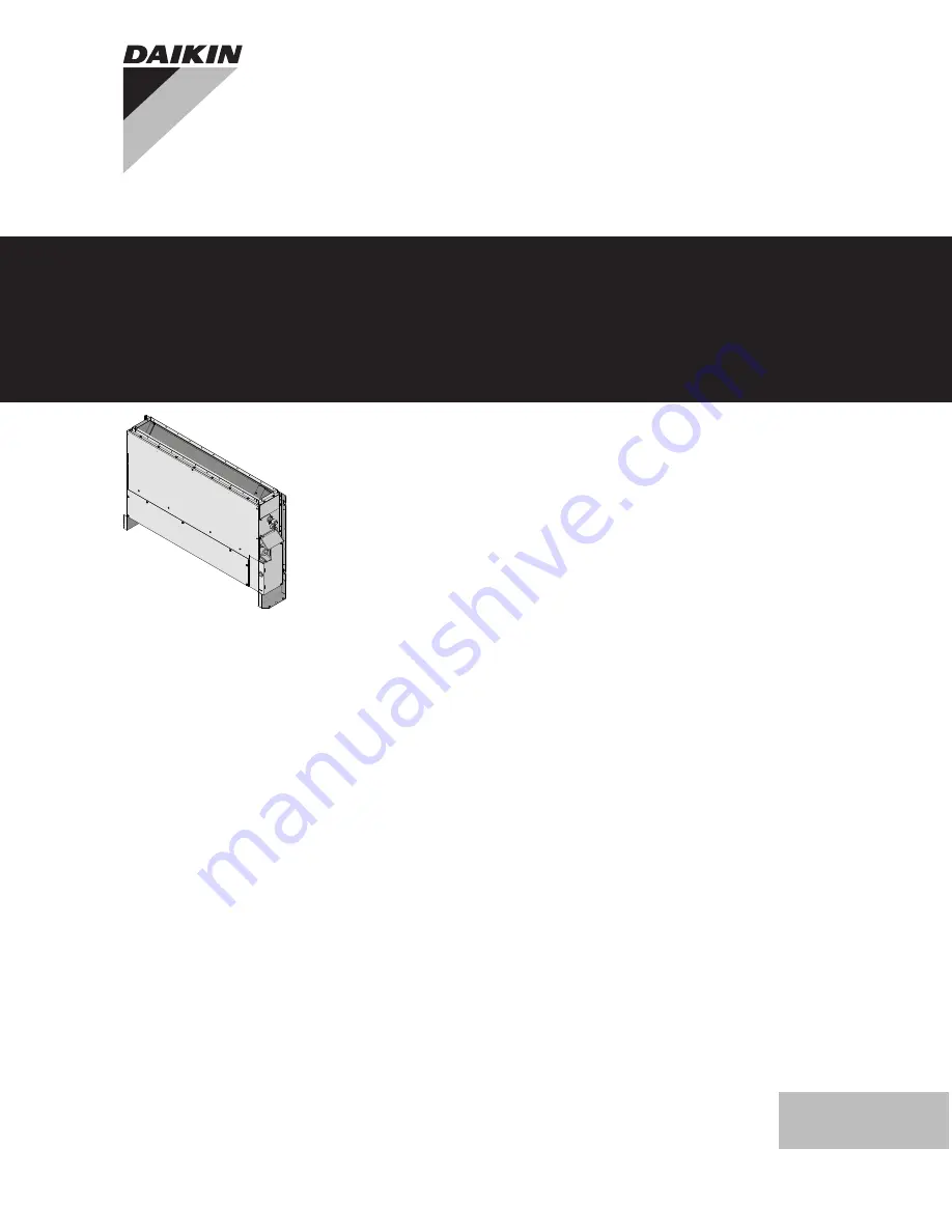
Split system air conditioners
English
FNA25A2VEBFNA35A2VEBFNA50A2VEBFNA60A2VEB
FNA25A2VEB9FNA35A2VEB9FNA50A2VEB9FNA60A2VEB9
Page 1: ...Installation manual Split system air conditioners English Installation manual Split system air conditioners FNA25A2VEB FNA35A2VEB FNA50A2VEB FNA60A2VEB FNA25A2VEB9 FNA35A2VEB9 FNA50A2VEB9 FNA60A2VEB9 ...
Page 2: ...itate cu instrucţiunile noastre skladni z naslednjimi standardi in drugimi normativi pod pogojem da se uporabljajo v skladu z našimi navodili on vastavuses järgmis t e standardi te ga või teiste normatiivsete dokumentidega kui neid kasutatakse vastavalt meie juhenditele съответстват на следните стандарти или други нормативни документи при условие че се използват съгласно нашите инструкции atitinka...
Page 3: ...ate cu instrucţiunile noastre skladni z naslednjimi standardi in drugimi normativi pod pogojem da se uporabljajo v skladu z našimi navodili on vastavuses järgmis t e standardi te ga või teiste normatiivsete dokumentidega kui neid kasutatakse vastavalt meie juhenditele съответстват на следните стандарти или други нормативни документи при условие че се използват съгласно нашите инструкции atitinka ž...
Page 4: ...commercial and household use by lay persons Documentation set This document is part of a documentation set The complete set consists of General safety precautions Safety instructions that you MUST read before installing Format Paper in the box of the indoor unit Indoor unit installation manual Installation instructions Format Paper in the box of the indoor unit Installer reference guide Preparatio...
Page 5: ...xcept for short service periods 1 4 1 1 Installation site requirements of the indoor unit INFORMATION The sound pressure level is less than 70 dBA Use suspension bolts for installation Mind the following requirements Wall mounted type Floor standing type a a a 1750 100 a a Minimum clearance Top view 300 300 1000 mm 20 a a Indoor unit Install the unit with a prebuilt fully enclosed casing with remo...
Page 6: ...0 660 50 60 1750 1060 A Maintenance area width B Air inlet grille width a Air outlet direction b Air inlet grille height c Air inlet direction External static pressure Refer to technical documentation to ensure that the unit s external static pressure is not exceeded Removing the legs If it is necessary to remove the legs follow these instructions b a 2 1 b A B A Bottom view B Side view a Protecti...
Page 7: ...or more rooms are connected to the unit using a duct system make sure there are no operating ignition sources example open flames an operating gas appliance or an operating electric heater in case the floor area is less than Amin specified in the General safety precautions no auxiliary devices which may be a potential ignition source are installed in the duct work example hot surfaces with a tempe...
Page 8: ... large sealing pad insulation around the metal clamp and drain hose and fix it with cable ties 6 Connect the drain piping to the drain hose 4 mm A A A A A A f 6 5 2 c e 4 b a d b a d c 3 1 2 6 1 a Drain pipe connection attached to the unit b Drain hose accessory c Metal clamp accessory d Large sealing pad accessory e Insulation piece drain pipe accessory f Drain piping field supply NOTICE Do NOT r...
Page 9: ...system with nitrogen gas up to a gauge pressure of at least 200 kPa 2 bar It is recommended to pressurize to 3000 kPa 30 bar in order to detect small leaks 2 Check for leaks by applying the bubble test solution to all connections 3 Discharge all nitrogen gas 5 3 Connecting the electrical wiring DANGER RISK OF ELECTROCUTION WARNING ALWAYS use multicore cable for power supply cables WARNING If the s...
Page 10: ...e NO missing phases or reversed phases The system is properly earthed and the earth terminals are tightened The fuses or locally installed protection devices are installed according to this document and have NOT been bypassed The power supply voltage matches the voltage on the identification label of the unit There are NO loose connections or damaged electrical components in the switch box The ins...
Page 11: ... interface Error code Possible cause Nothing displayed the currently set temperature is not displayed The wiring is disconnected or there is a wiring error between power supply and outdoor unit between outdoor unit and indoor units between indoor unit and user interface The fuse on the outdoor or indoor unit PCB has blown A0 Refrigerant leak detected 1 CH Abnormality of refrigerant leakage sensor ...
Page 12: ... HEATER F U FU FOR CHARACTERISTICS FUSE REFER TO PCB INSIDE YOUR UNIT FG CONNECTOR FRAME GROUND H HARNESS H P LED V L PILOT LAMP LIGHT EMITTING DIODE HAP LIGHT EMITTING DIODE SERVICE MONITOR GREEN HIGH VOLTAGE HIGH VOLTAGE IES INTELLIGENT EYE SENSOR IPM INTELLIGENT POWER MODULE K R KCR KFR KHuR K M MAGNETIC RELAY L LIVE L COIL L R REACTOR M STEPPER MOTOR M C COMPRESSOR MOTOR M F FAN MOTOR M P DRAI...
Page 13: ......
Page 14: ......
Page 15: ......
Page 16: ...4P456958 1D 2018 11 Copyright 2017 Daikin ...