Installer reference guide
Daikin Altherma – Low temperature split
English
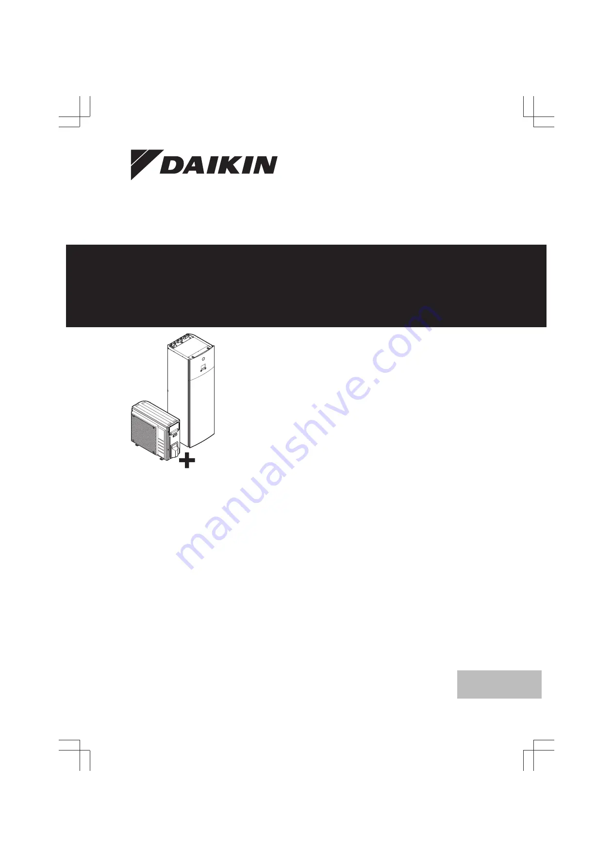
ERGA04DAV3(A)ERGA06DAV3(A)ERGA08DAV3(A)
EHVH04S23DAV(G)EHVH08S23DAV(G)
Page 1: ...staller reference guide Daikin Altherma Low temperature split English Installer reference guide Daikin Altherma Low temperature split ERGA04DAV3 A ERGA06DAV3 A ERGA08DAV3 A EHVH04S23DAV G EHVH08S23DAV...
Page 2: ...ents 25 6 3 2 Refrigerant piping insulation 25 6 4 Preparing water piping 25 6 4 1 Water circuit requirements 25 6 4 2 Formula to calculate the expansion vessel pre pressure 26 6 4 3 To check the wate...
Page 3: ...11 Maintenance and service 78 11 1 Overview Maintenance and service 78 11 2 Maintenance safety precautions 78 11 3 Checklist for yearly maintenance of the outdoor unit 79 11 4 Checklist for yearly mai...
Page 4: ...to return to normal temperature If you must touch it wear protective gloves Do NOT touch any accidental leaking refrigerant WARNING Provide adequate measures to prevent that the unit can be used as a...
Page 5: ...t may only be charged after performing the leak test and the vacuum drying In case re charge is required refer to the nameplate of the unit It states the type of refrigerant and necessary amount The u...
Page 6: ...established When disconnecting the power supply the current carrying connections must be separated before the earth connection is The length of the conductors between the power supply stress relief an...
Page 7: ...n What to do and know before going on site Installation What to do and know to install the system Configuration What to do and know to configure the system after it is installed Commissioning What to...
Page 8: ...gases label d Energy label e Unit mounting plate f Bolts nuts washers spring washers and wire clamp 3 3 Indoor unit 3 3 1 To unpack the indoor unit 1 2 8 3 3 2 To remove the accessories from the indo...
Page 9: ...t The drain pan kit consists of Drain pan Installation brackets For installation instructions see the installation manual of the drain pan Drain pan heater EKDPH008CA The drain pan heater is required...
Page 10: ...onnect either the remote indoor sensor or the remote outdoor sensor PC cable EKPCCAB The PC cable makes a connection between the switch box of the indoor unit and a PC It gives the possibility to upda...
Page 11: ...d based on the ambient temperature of the user interface Number of water temperature zones 4 4 Code 7 02 0 Single zone Main Benefits Highest comfort and efficiency The smart room thermostat functional...
Page 12: ...directly connected to the indoor unit The desired room temperature is set via the remote controller of the heat pump convectors The space heating demand signal is sent to one digital input on the ind...
Page 13: ...r piping on page 25 The user interface connected on the indoor unit decides the space operation mode Mind that the operation mode on each room thermostat must be set to match the indoor unit The room...
Page 14: ...ntrol 2 9 Code C 07 0 Leaving water Unit operation is decided based on the leaving water temperature Number of water temperature zones 4 4 Code 7 02 0 Single zone Main 5 2 3 Multiple rooms Two LWT zon...
Page 15: ...r systems provides the excellent heating comfort of the under floor heating and the rapid air heat up of the heat pump convectors e g living room under floor heating and the bedroom convector no conti...
Page 16: ...anually operated contact Setup Connect the following field wiring L N H Com A K2A K1A X2M BTI K2A K1A Indoor Auto Boiler 35 30 X Y Indoor BTI Boiler thermostat input A Auxiliary contact normal closed...
Page 17: ...sinfection function for the DHW tank is active Can assist during defrost operation for the outdoor unit The higher the outdoor temperature the better the performance of the heat pump If energy prices...
Page 18: ...ent of the anti legionella heater and set the capacity via the user interface Example If you measure an anti legionella heater resistance of 24 the capacity of the heater at 230 V is 2200 W 5 5 2 Cons...
Page 19: ...easures the rest i e indoor unit optional backup heater and anti legionella heater Setup Connect power meter 1 to X5M 5 and X5M 6 Connect power meter 2 to X5M 3 and X5M 4 Power meter types Power meter...
Page 20: ...ponding power limitation level DI1 weakest limitation highest energy consumption DI4 strongest limitation lowest energy consumption For the specifications of the digital inputs and for where to connec...
Page 21: ...es As a result the outdoor ambient temperature is NOT read out If the desired leaving water temperature is weather dependent the full time outdoor temperature measurement is important This is another...
Page 22: ...It is NOT recommended to install the unit in the following places because it may shorten the life of the unit Where the voltage fluctuates a lot In vehicles or vessels Where acidic or alkaline vapour...
Page 23: ...n hose to the drain on page 34 It requires to remove one or both side panels The foundation must be strong enough to bear the weight of the unit Take the weight of the unit with a domestic hot water t...
Page 24: ...your dealer Use table 3 in chapter Technical data and dm to calculate the minimum opening area for natural ventilation between room A and room B VAmin cm2 Unit can be installed at room A if 2 ventilat...
Page 25: ...se excessive force when connecting the piping Deformation of the piping can cause malfunctioning of the unit Connecting piping Tools Only use appropriate tooling to handle brass which is a soft materi...
Page 26: ...ed with fresh water This procedure must be repeated at least once a day the first 5 consecutive days after installation Domestic hot water tank Standstills In cases where during longer periods of time...
Page 27: ...ndoor unit is too small for the installation In this case it is recommended to install an extra vessel outside the unit a This is the height difference m between the highest point of the water circuit...
Page 28: ...al shock or fire Do NOT install a phase advancing capacitor because this unit is equipped with an inverter A phase advancing capacitor will reduce performance and may cause accidents WARNING All wirin...
Page 29: ...ional equipment 6 User interface used as room thermostat 2 e 7 Room thermostat 3 or 4 100 mA b 8 Outdoor ambient temperature sensor 2 b 9 Indoor ambient temperature sensor 2 b Item Description Wires M...
Page 30: ...connect the refrigerant piping to the outdoor unit on page 37 and 7 9 6 To connect the electrical wiring on the outdoor unit on page 42 7 2 3 To open the indoor unit 1 Remove the top panel 5 T25 2 Rem...
Page 31: ...and wind by installing a snow cover and baffle plates See Preparing installation site in 6 Preparation on page 21 7 3 2 Precautions when mounting the outdoor unit INFORMATION Also read the precautions...
Page 32: ...l height b EKFT008D option kit Option 4 On brackets to the wall with the EKFT008D option kit The EKFT008D option kit is recommended in areas with heavy snowfall 250 300 250 mm a b c 4 a Maximum snowfa...
Page 33: ...stall a waterproof plate within 150 mm of the bottom side of the unit in order to prevent water from getting into the unit and to avoid drain water dripping see the following figure NOTICE If the drai...
Page 34: ...tdoor and indoor unit before you can connect the refrigerant and water piping Typical workflow Mounting the indoor unit typically consists of the following stages 1 Installing the indoor unit 7 4 2 Pr...
Page 35: ...precautions Preparation DANGER RISK OF BURNING CAUTION Do NOT use mineral oil on flared part Do NOT reuse piping from previous installations NEVER install a drier to this R32 unit to guarantee its li...
Page 36: ...pe Conventional flare tool Clutch type Ridgid type Wing nut type Imperial type A 0 0 5 mm 1 0 1 5 mm 1 5 2 0 mm 5 Check that the flaring is properly made a b c a Flare s inner surface MUST be flawless...
Page 37: ...nd check for refrigerant leaks Item Tightening torque N m Stem cap liquid side 13 5 16 5 Stem cap gas side 22 5 27 5 To handle the service cap ALWAYS use a charge hose equipped with a valve depressor...
Page 38: ...o the service port of the gas stop valve Make sure that the gas stop valve and liquid stop valve are firmly closed before performing the leak test or vacuum drying 7 6 3 To check for leaks NOTICE Do N...
Page 39: ...ng refrigerant typically consists of the following stages 1 Determining how much refrigerant to charge 2 Charging refrigerant 3 Filling in the fluorinated greenhouse gases label and fixing it to the i...
Page 40: ...water piping INFORMATION Also read the precautions and requirements in the following chapters General safety precautions Preparation 7 8 3 To connect the water piping NOTICE Do NOT use excessive forc...
Page 41: ...l air is purged 4 Check for water leaks 5 Manually operate the field installed pressure relief valve to ensure a free water flow through the discharge pipe NOTICE To operate the system the domestic ho...
Page 42: ...ations of standard wiring components Component ERGA04 06D AV3 ERGA08DAV3 ERGA04 08D AV3A Power supply cable MCA a 19 9 A 24 0 A 15 9 A Voltage 230 V Phase 1 Frequen cy 50 Hz Wire sizes Must comply wit...
Page 43: ...gerant gas pipe Routing Possible cables depending on unit type and installed options a Low voltage Preferential power supply contact User interface used as room thermostat option Power consumption dig...
Page 44: ...ntial kWh rate power supply contact is connected to the same terminals X5M 9 10 as the safety thermostat It is only possible for the system to have EITHER preferential kWh rate power supply OR a safet...
Page 45: ...onnect the changeover to external heat source cable to the appropriate terminals as shown in the illustration below X1M X2M A4P X5M X1M YC Y1 Y2 Y3 Y4 X2 X1 X2M X4 X3 N L a a Installation of EKRP1HB i...
Page 46: ...th cable Make sure that the power supply is in accordance with the anti legionella heater capacity as listed in the table below Anti legionella heater capacity Power supply Maximum running current 2 4...
Page 47: ...ings Code See also To access the installer settings on page 47 8 6 Menu structure Overview installer settings on page 74 8 1 1 To access the most used commands To change the user permission level You...
Page 48: ...le Schedule 2 1 Additional zone only if 4 4 1 Emitter type 3 7 8 4 4 Additional zone on page 56 Control read only 3 9 Setpoint mode 3 4 Heating WD curve 3 5 if applicable Schedule 3 1 Tank Heat up mod...
Page 49: ...text in case of a malfunction on page 85 for more information Item Description Room Restriction Only displayed if a room thermostat is connected to the indoor unit Set the room temperature Main zone...
Page 50: ...1 Y2 X2 Y a X Possible actions on this screen Go through the temperatures Change the temperature Go to the next temperature Confirm changes and proceed Item Description a Possible weather dependent zo...
Page 51: ...fined 1 2 Select Copy Edit Copy Result C is displayed next to the copied day 3 Select Tuesday Mon Sat Wed Fri Thu Tue Sun User defined 1 C 4 Select Paste Copy Paste C Result Mon Sat Wed Fri Thu Tue Su...
Page 52: ...1 4 1 1 Room Antifrost Activation Yes Set the room antifrost setpoint 1 4 2 Room Antifrost Room setpoint NOTICE If the system does NOT contain a backup heater then Make sure that the room antifrost c...
Page 53: ...sensor offset ONLY applicable in case of room thermostat control You can calibrate the external room temperature sensor It is possible to give an offset to the room thermistor value measured by the us...
Page 54: ...t water temperature is configured as the main zone and the zone with the highest water temperature is configured as the additional zone Not configuring the system in this way could cause damage to the...
Page 55: ...l inputs X2M 35 and X2M 34 Select this value in case of a connection to the wired EKRTWA or wireless EKRTR1 room thermostat Leaving water temperature Delta T The target delta T in heating for the main...
Page 56: ...he minimum leaving water temperature setpoint required to reach a stable condition on the comfort setpoint for the room To increase efficiency modulation can lower the leaving water setpoint By settin...
Page 57: ...Description Leaving water temperature range for the additional leaving water temperature zone the leaving water temperature zone with the highest leaving water temperature in heating operation 3 8 1 9...
Page 58: ...rs CAUTION If there are 2 zones and the emitter types are wrongly configured water of high temperature can be sent towards a low temperature emitter underfloor heating To avoid this Install an aquasta...
Page 59: ...o actuators When there is no heating output the pump speed limitation is applicable When there is heating output the pump speed is only determined by delta T in relation to the required capacity With...
Page 60: ...ful operation is active the risk of space heating and capacity shortage comfort problems is significant In case of frequent domestic hot water operation frequent and long space heating interruptions w...
Page 61: ...ture shall be selected according to the applicable legislation CAUTION Be sure that the disinfection function start time 5 7 3 with defined duration 5 7 5 is NOT interrupted by possible domestic hot w...
Page 62: ...ge economic and reheat temperature are NOT weather dependent In case of Reheat only domestic hot water preparation the desired tank temperature is weather dependent according to the weather dependent...
Page 63: ...de To check if holiday mode is activated and or running If is activated on the home screen holiday mode is active To configure the holiday 1 Activate the holiday mode Go to 7 3 1 User settings Holiday...
Page 64: ...ken into account when setting the energy prices Although the running cost can increase the total operation cost taking into account the reimbursement will be optimized NOTICE Make sure to modify the s...
Page 65: ...turn valve f Shower g Cold water h Domestic hot water OUT i Recirculation connection j Anti legionella heater DHW pump schedule Here you can program a schedule for the DHW pump only for field supplied...
Page 66: ...heater you can set the exact heater capacity and this will lead to more accurate energy data Code Description 9 4 1 6 02 Capacity kW Only applies to domestic hot water tank with an internal anti legio...
Page 67: ...n serve as an emergency heater and either automatically or non automatically take over the heat load When auto emergency is set to Automatic and a heat pump failure occurs the optional backup heater w...
Page 68: ...preset value is only taken into account if there is a request for space heating If there is NO request for space heating the tank is heated until the setpoint has been reached When Control Room therm...
Page 69: ...r unit is connected to a normal kWh rate power supply via X2M 5 6 and the optional backup heater is NOT connected to the preferential kWh rate power supply 9 8 3 D 05 Allow pump 0 No Pump is forced of...
Page 70: ...select None to indicate the corresponding pulse input is NOT used Code Description 9 A 1 D 08 Electricity meter 1 0 None NOT installed 1 1 10kWh Installed 2 1 kWh Installed 3 10 kWh Installed 4 100 kW...
Page 71: ...follows Code Description 9 C 2 7 05 0 Very high 1 High 2 Medium 3 Low 4 Very low Possibility 1 Based on the outdoor temperature Set all electricity prices 7 5 1 7 5 3 to 0 in the menu structure Also s...
Page 72: ...function Defines whether the outdoor unit power supply can be interrupted internally by indoor unit control during stand still conditions no space heating cooling nor domestic hot water demand The fi...
Page 73: ...rofile 7 3 Holiday Activation From Till 7 4 Quiet Activation Schedule 7 5 Electricity price High Medium Low Schedule 7 2 Time date Hours Minutes Year Month Day Daylight savings time Format 1 4 Antifro...
Page 74: ...mer Operation 9 2 Domestic hot water Domestic hot water DHW pump DHW pump schedule Solar 9 9 Power consumption control Power consumption control Type Limit Limit 1 Limit 2 Limit 3 Limit 4 Priority hea...
Page 75: ...ll below checks are fulfilled the unit MUST be closed ONLY then can the unit be powered up You read the complete installation instructions as described in the installer reference guide The indoor unit...
Page 76: ...d from the system During air purge function pump speed limitation 9 0D is NOT applicable The air purge function automatically stops after 30 minutes To perform a manual air purge Conditions Make sure...
Page 77: ...It allows the installer to program and execute this program Conditions Make sure all operation is disabled Go to the Operation menu and turn off Room Space heating cooling and Tank operation INFORMATI...
Page 78: ...Start in the UFH screed dryout screen 2 Open the menu and select Stop UFH screed dryout 3 Select OK to confirm Result The underfloor heating screed dryout is stopped When the program is stopped due t...
Page 79: ...eparator by closing the shut off valves To properly empty the dirt separator sufficient pressure is required To prevent dirt from remaining in the dirt separator ALWAYS take off the magnetic sleeve AL...
Page 80: ...le legislation requires a chemical disinfection in specific situations involving the domestic hot water tank please be aware that the domestic hot water tank is a stainless steel cylinder We recommend...
Page 81: ...he magnetic filter dirt separator is ONLY required in case of severe issues Preferably this action is never to be done during the complete lifetime of the magnetic filter dirt separator a b a Bottom p...
Page 82: ...ve action The water flow is too low Check and make sure that All shut off valves of the water circuit are completely open The water filter is clean Clean if necessary There is no air in the system Pur...
Page 83: ...ormed by the installer If you purge air from the heat emitters or collectors mind the following WARNING Air purging heat emitters or collectors Before you purge air from heat emitters or collectors ch...
Page 84: ...d for heating domestic hot water Check and make sure that the space heating priority settings have been configured appropriately Make sure that the space heating priority status has been enabled Go to...
Page 85: ...roblem H0 00 OU Voltage current sensor problem H3 00 OU Malfunction of high pressure switch HPS H6 00 OU Malfunction of position detection sensor H8 00 OU Malfunction of compressor input CT system H9...
Page 86: ...disinfection function to preheat the tank INFORMATION If the anti legionella heater overheats and is disabled by the thermostatic safety the unit will not give an error directly Check if the anti leg...
Page 87: ...ng on page 87 4 After 5 to 10 minutes after only 1 or 2 minutes in case of very low ambient temperatures 10 C close the liquid stop valve with a hexagonal wrench 5 Check on the manifold if the vacuum...
Page 88: ...4 CuT 6 4 CuT 6 4 CuT 6 4 CuT 4 0 CuT 4 0 CuT 9 5 CuT 15 9 CuT 3D110394 9 5 CuT 12 7 CuT 15 9 CuT 6 4 CuT S1PH Y1E R1T R3T M1C Y1S 4 0 CuT M1F b a c d e f g h i j k k g g a Field piping liquid 6 4 mm...
Page 89: ...ating mode condenser c2 Liquid refrigerant OUT heating mode condenser d1 Liquid refrigerant IN cooling mode evaporator d2 Gas refrigerant OUT cooling mode evaporator e Plate heat exchanger f Shut off...
Page 90: ...WHT white GRN green YLW yellow 3 Legend AL Connector C Capacitor DB Rectifier bridge DC Connector DP Connector E Connector F1U Fuse T 6 3 A 250 V FU1 FU2 Fuse T 3 15 A 250 V FU3 Fuse T 30 A 250 V H Co...
Page 91: ...tat wired On OFF thermostat wired On OFF thermostat wireless On OFF thermostat wireless Ext thermistor External thermistor Heat pump convector Heat pump convector Position in switch box English Transl...
Page 92: ...lse detection voltage supplied by PCB 230 V AC supplied by PCB 230 V AC supplied by PCB Continuous Continuous current DHW pump output Domestic hot water pump output DHW pump Domestic hot water pump En...
Page 93: ...g mode Ext heat source e g boiler Alarm indication 2 core 2 core signal 2 core signal signal 2 core 2 core 2 core signal 2 core 2 core External sensor floor or ambient Only for KRTETS signal 2 core 3m...
Page 94: ...08 1 90 30 72 INFORMATION For floorstanding models the value of Installation height H is considered 600 mm to comply to IEC 60335 2 40 2013 A1 2016 Clause GG2 For intermediate mc values i e when mc i...
Page 95: ...he product and or operates the product Applicable legislation All international European national and local directives laws regulations and or codes that are relevant and applicable for a certain prod...
Page 96: ...1 9 Field settings table 8 7 5 7401 Applicable indoor units EHVH04S23DAV EHVH08S23DAV Notes 4P499575 1A 2017 11...
Page 97: ...2 Radiator Setpoint range 3 8 1 9 05 R W 15 37 C step 1 C 25 C 3 8 2 9 06 R W 2 0D 2 37 65 step 1 C 55 C 2 0D 2 37 55 step 1 C 55 C Additional zone 3 A C 06 R W 0 1 1 contact 2 2 contacts Delta T 3 B...
Page 98: ...0B R W 35 6 0E C step 1 C 55 C 5 C 0 0C R W 45 6 0E C step 1 C 65 C 5 C 0 0D R W 10 25 C step 1 C 15 C 5 C 0 0E R W 40 5 C step 1 C 10 C Tank 5 D 6 01 R W 0 10 C step 1 C 2 C User settings Quiet 7 4...
Page 99: ...No 1 Yes Back up heater 9 3 1 E 03 R W 0 No heater 1 External heater 2 3V 3 6V 4 9W 9 3 2 5 0D R O 0 2 0 230V 1 9 3 3 4 0A R O 0 3 0 1 9 3 4 6 03 R W 0 10kW step 0 2kW 3kW 9 3 5 6 04 R O 0 10kW step 0...
Page 100: ...0 5 kW 20 kW 9 9 B 5 0B R W 0 20 kW step 0 5 kW 20 kW 9 9 C 5 0C R W 0 20 kW step 0 5 kW 20 kW 9 9 D 4 01 0 None 1 BSH 2 BUH Energy metering 9 A 1 D 08 R W 0 No 1 0 1 pulse kWh 2 1 pulse kWh 3 10 pul...
Page 101: ...2 18 C step 0 5 C 12 C 9 I 3 08 35 9 I 3 09 15 9 I 4 00 R W 0 Disabled 1 Enabled 2 Only DHW What is the desired delta T in heating for the additional zone What is the desired delta T in heating for th...
Page 102: ...5 95 min step 5 min 30 min 9 I 8 02 R W 0 10 hour step 0 5 hour 3 hours 9 I 8 03 R W 20 95 min step 5 min 50 min The temperature difference determining the heat pump OFF temperature What is the capaci...
Page 103: ...onsmp ctrl 9 I D 05 R W 0 Forced off 1 As normal 9 I D 07 R W 0 No 1 Yes 9 I D 08 R W 0 No 1 0 1 pulse kWh 2 1 pulse kWh 3 10 pulse kWh 4 100 pulse kWh 5 1000 pulse kWh 9 I D 09 R W 0 No 1 0 1 pulse k...
Page 104: ...09 R W 0 Disabled 1 Enabled 9 I F 0A 0 9 I F 0B R W 0 No 1 Yes 9 I F 0C 1 9 I F 0D R W 0 Continuous 1 Sample 2 Request Which type of unit is installed Which type of compressor is installed What is the...
Page 105: ......
Page 106: ......
Page 107: ......
Page 108: ...4P499573 1A 2018 11 Copyright 2017 Daikin...