5 Piping installation
Installation manual
15
EL23E
Daikin Altherma 3 R MT F
4P708476-1 – 2023.03
Pipe outer diameter
(Ø
p
)
Insulation inner
diameter (Ø
i
)
Insulation thickness
(t)
6.4 mm (1/4")
8~10 mm
10 mm
15.9 mm (5/8")
16~20 mm
13 mm
Ø
i
Ø
i
t
Ø
p
Ø
p
If the temperature is higher than 30°C and the humidity is higher
than RH 80%, the thickness of the insulation materials should be at
least 20 mm to prevent condensation on the surface of the
insulation.
5.2
Connecting refrigerant piping
See the installation manual of the outdoor unit for all guidelines,
specifications and installation instructions.
5.2.1
To connect the refrigerant piping to the
indoor unit
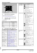
1
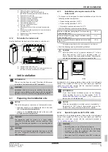
Connect the liquid stop valve from the outdoor unit to the
refrigerant liquid connection of the indoor unit.
b
a
a
Refrigerant liquid connection
b
Refrigerant gas connection
2
Connect the gas stop valve from the outdoor unit to the
refrigerant gas connection of the indoor unit.
5.3
Preparing water piping
NOTICE
In case of plastic pipes, make sure they are fully oxygen
diffusion tight according to DIN 4726. The diffusion of
oxygen into the piping can lead to excessive corrosion.
NOTICE
Water circuit requirements.
Make sure to comply with the
water pressure and water temperature requirements
below. For additional water circuit requirements, see the
installer reference guide.
▪
Water pressure – Domestic hot water.
The maximum water
pressure is 10 bar (=1.0 MPa), and must be in accordance with
the applicable legislation. Provide adequate safeguards in the
water circuit to ensure that the maximum pressure is NOT
exceeded (see
"5.4.1 To connect the water piping"
16]). The
minimum water pressure to operate is 1 bar (=0.1 MPa).
▪
Water pressure –
Space heating/cooling circuit.
The maximum
water pressure is 3 bar (=0.3 MPa). Provide adequate safeguards
in the water circuit to ensure that the maximum pressure is NOT
exceeded. The minimum water pressure to operate is 1 bar
(=0.1 MPa).
▪
Water temperature.
All installed piping and piping accessories
(valve,
connections,…)
MUST
withstand
the
following
temperatures:
INFORMATION
The following figure is an example and may NOT
completely match your system layout
EXAMPLE
(*) Maximum temperature for piping and accessories
5.3.1
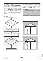
To check the water volume and flow rate
Minimum water volume
Check that the total water volume in the installation is higher than
the minimum water volume, the internal water volume of the indoor
unit NOT included:
If…
Then the minimum water
volume is…
Cooling operation
21 l
Heating operation
21 l
NOTICE
When circulation in each space heating/cooling loop is
controlled by remotely controlled valves, it is important that
the minimum water volume is guaranteed, even if all of the
valves are closed.
Minimum flow rate
Check that the minimum flow rate in the installation is guaranteed in
all conditions on each zone separately. For this purpose, use the
differential pressure bypass valve delivered with the unit, and
respect the minimum water volume.
If operation is…
Then the minimum required
flow rate is…
Cooling
10 l/min
Heating/defrost
20 l/min
NOTICE
When circulation in each or certain space heating loops is
controlled by remotely controlled valves, it is important that
the minimum flow rate is guaranteed, even if all valves are
closed. In case the minimum flow rate cannot be reached,
a flow error 7H will be generated (no heating or operation).
See the installer reference guide for more information.
See the recommended procedure as described in

