3
8. Locate 9-pin plug in unit.
9. Connect the plug to the maiting 9-pin plug attached to heater kit
(Figure 4).
10. Install blower door and horizontal supply cover if it was removed.
11. Reconnect power.
12. Set up a required airflow - CFM for your unit with electic heater
by selecting a proper speed tap. For details see Air Flow Ad-
justment chapter in IOD-1032 for DRC and DRH models or in
IOD-1043 for DBC and DBG models.
• Refer to Air Flow for Electric Heat table in this document to identi-
fy minimum required CFM for your unit with specific heater model.
• Refer to Appendix A - Blower Performance Tables for speed tap
selection in IOD-1032 for DRC and DRH models or in IOD-1043
for DBC and DBH models.
13. Close control box door.
14. Reconnect power to the unit.
15. Test unit to ensure it is functioning properly.
16. Place Heater wiring diagram beside unit diagram.
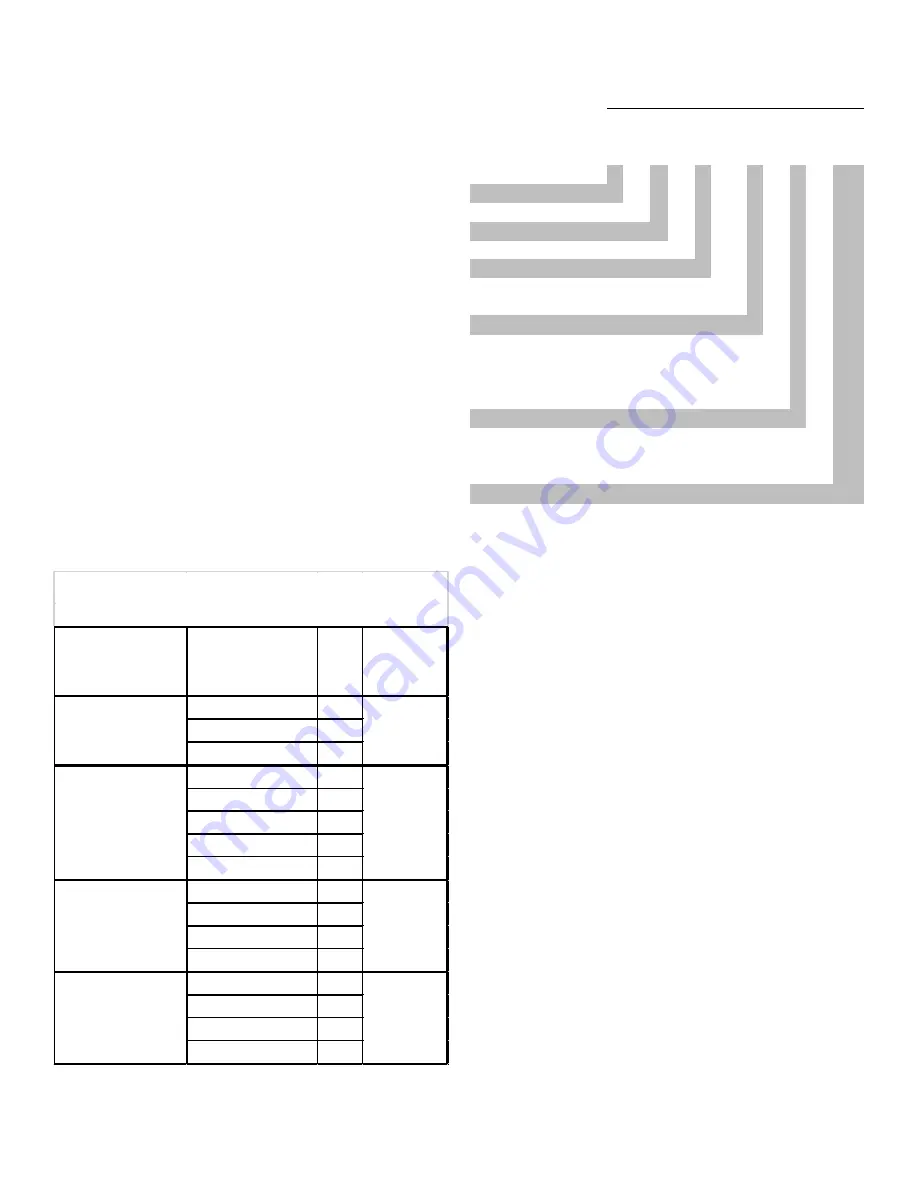
UNITS
HEATER KIT
MODEL NUMBER kW
MINIMUM
SCFM
EH*-*S05
5
EH*-*S10
10
EH*-*S15
15
EH*-*S05
5
EH*-*S10
10
EH*-*S15
15
EH*-*S18
18
EH*-*S20
20
EH*-*S05
5
EH*-*S10
10
EH*-*S15
15
EH*-*S20
20
EH*-*S05
5
EH*-*S10
10
EH*-*S15
15
EH*-*S20
20
1950
AIR FLOW FOR ELECTRIC HEAT
DRC060, DRH060,
DBC060, DBH060
DRC036, DRH036,
DBC036, DBH036
DRC048, DRH048,
DBC048, DBH048
975
1300
1625
DRC072, DRH072,
DBC072, DBH072
HEATER KIT MODEL NUMBER NOMENCLATURE
E
H
*
-
*
S
15
1
2
3
-
4
5
6, 7
Electric
Heater
Heater Type
X
Staged
S
SCR (modulating)
Voltage
1
208-230/1/60
Single phase 60 Hz
3
208-230/3/60
Three phase 60 Hz
4
460/3/60
Three phase 60 Hz
7
575/3/60
Three phase 60 Hz
Chassis
S
Small
M
Medium
L
Large
Kilowatt
5
5 kW
10
10 kW
15
15 kW
18
18 KW
20
20 kW
30
30 kW


