background image

4

WARNING

If the information in these instructions is not followed 

exactly, a fire or explosion may result causing property 

damage, personal injury or loss of life. 

- do not store or use gasoline or other flammable vapors 

and liquids in the vicinity of this or any other appliance. 

- WHAT TO DO IF YOU SMELL GAS: 

• Do not try to light any appliance.

• Do not touch any electrical switch; do not use any 

phone in your building. 

• Immediately call your gas supplier from a neighbor’s 

phone. Follow the gas supplier’s instructions. If 

you cannot reach your gas supplier, call the fire 

department. 

- Installation and service must be performed by a qualified 

installer, service agency or the gas supplier. 

WARNING

Heating unit should not be utilized without reasonable, 

routine, inspection, maintenance and supervision. If the 

building in which any such device is located will be vacant, 

care should be taken that such device is routinely inspected, 

maintained and monitored. In the event that the building 

maybe exposed to freezing temperatures and will be vacant, 

all water-bearing pipes should be drained, the building 

should be properly winterized, and the water source closed. 

In the event that the building may be exposed to freezing 

temperatures and will be vacant, any hydronic coil units 

should be drained as well and, in such case, alternative heat 

sources should be utilized. 

WARNING

To prevent possible property damage, personal injury or 

death due to electrical shock, the furnace must be located 

to protect the electrical components from water.

Drain  trap  must  be  primed  at  time  of  installation.  Trap  is 

internally partitioned; add water to both inlet ports until water 

appears at both sides of the outlet opening. Failure to prime 

trap  at  time  of  installation  may  have  a  negative  effect  on 

combustion quality and pressure switch action.

B10259-216

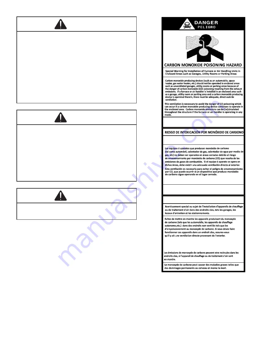
CO can cause serious illness including permanent brain

damage or death.

Advertencia especial para la instalación de calentadores ó manejadoras 

de aire en áreas cerradas como estacionamientos ó cuartos de servicio.

B10259-216

El monóxido de carbono puede causar enfermedades severas 

como  daño cerebral permanente ó muerte.

Las emisiones de monóxido de carbono pueden circular a través

del aparato cuando se opera en cualquier modo. 

B10259-216

RISQUE D'EMPOISONNEMENT AU MONOXYDE DE CARBONE

Cette ventilation est nécessaire pour éviter le danger d'intoxication

au CO pouvant survenir si un appareil produisant du monoxyde 

de carbone continue de fonctionner au sein de la zone confinée.

Shipping Inspection

All units are securely packed in shipping containers 

tested according to International Safe Transit Association 

specifications. The carton must be checked upon arrival for 

external damage. If damage is found, a request for inspection 

by carrier’s agent must be made in writing immediately.

The furnace must be carefully inspected on arrival for 

damage and bolts or screws which may have come loose in 

transit. In the event of damage the consignee should:

1. 

Make a notation on delivery receipt of any visible 

damage to shipment or container.

Summary of Contents for DM92SS

Page 1: ...THIS SYMBOL AS A SAFETY PRECAUTION TABLE OF CONTENTS Safety Considerations 3 Shipping Inspection 4 Electrostatic Discharge ESD Precautions 5 To The Installer 5 Product Application 5 Location Requirem...

Page 2: ...26 High Altitude Derate 26 Propane Gas Conversion 26 Gas Piping Connections 26 Gas Piping Checks 29 Propane Gas Tanks and Piping 29 Circulating Air Filters 29 Duct work Air Flow 29 Checking Duct Stati...

Page 3: ...gas fired furnace for installation in a residential garage must be installed as specified in the LOCATION REQUIREMENTS AND CONSIDERATIONS section of this manual This furnace may be used as a construc...

Page 4: ...electrical shock the furnace must be located to protect the electrical components from water Drain trap must be primed at time of installation Trap is internally partitioned add water to both inlet po...

Page 5: ...ith static electricity i e do not move or shuffle your feet do not touch ungrounded objects etc If you come in contact with an ungrounded object repeat step 2 before touching control or wires 4 Discha...

Page 6: ...and the service area around the unit must have flooring To ensure proper furnace operation install operate and maintain the furnace in accordance with these installation and operation instructions al...

Page 7: ...above substances This protects the non direct vent furnace from airborne contaminants To ensure that the enclosed non direct vent furnace has an adequate supply of combustion air vent from a nearby u...

Page 8: ...nting system may be too large to properly vent the remaining attached appliances POSITION SIDES REAR FRONT BOTTOM FLUE TOP Upflow 0 0 3 C 0 1 Horizontal 6 0 3 C 0 6 C If placed on combustible floor fl...

Page 9: ...ant l un des essais d crits ci dessus des correctifs doivent tre apport s au syst me de ventilation conform ment au National Fuel Gas Code ANSI Z223 1 NFPA 54 et ou au Code d installation du gaz natur...

Page 10: ...tal counterflow furnaces return ductwork must be attached to the basepan top end of the blower compartment NOTE Ductwork must never be attached to the back of the furnace Contact your distributor for...

Page 11: ...gy content difference between natural and propane gas High Stage Low Stage Natural None 45 3 5 w c 1 9 w c None Propane LPM 07 1 1 25mm 10 0 w c 6 0 w c None Gas Altitude Kit Orifice Manifold Pressure...

Page 12: ...aterials and Joining Methods Two three inch nominal diameter PVC Schedule 40 pipe meeting ASTM D1785 PVC primer meeting ASTM F656 and PVC solvent cement meeting ASTM D2564 specifications must be used...

Page 13: ...es above ground level or the anticipated snow level Vent terminations non direct and direct vent must terminate at least 3 feet above any forced air inlet located within 10 feet NOTE This provision do...

Page 14: ...pipe Secure vent flue pipe directly into the furnace fitting with the appropriate glue Alternately a small section of 2 pipe may be glued in the furnace socket and a rubber coupling installed to allow...

Page 15: ...er outlet 5 Install cut end of the flanged section and connect to inducer with rubber coupling supplied with furnace Install screws removed in step 1 securing flange to cabinet MODEL PIPE SIZE 1 2 3 4...

Page 16: ...per material manufacturers specifications to prevent separation and flue gas leaks Figure 11 Insert flange Cut 2 long R 000142 F Figure 9 CUT HERE Figure 10 Vent Flue Pipe Cuts Upflow Horizontal model...

Page 17: ...secured to the combustion air intake to prevent inadvertent blockage The tee used in the vent flue termination must be included when determining the number of elbows in the piping system Vent Flue Pi...

Page 18: ...r specific details on termination construction For details concerning connection of pipes to the furnace refer to the Vent Flue Pipe and Combustion Pipe Standard Furnace Connections or Alternate Furna...

Page 19: ...ecifications Condensate Drain Lines Drain Trap Acondensing gas furnace achieves its high level of efficiency by extracting heat from the products of combustion to the point where condensation takes pl...

Page 20: ...ay be added in the area shown in Figure 21 Any unused cabinet opening must be sealed Do not allow drain hose to sag or trap water Figure 21 Drain Exiting Right Side 1 Locate and Install the 45 pipe ho...

Page 21: ...the top mounting tabs of the trap into the two predrilled holes in the side of the cabinet 9 Refer to Field Supplied Drain section for instructions on field supplied installed drain on outlet of furn...

Page 22: ...he non grommet end Discard the section without the grommet 5 Insert the cut end of tube 5 through the lower cabinet drain hole 6 Insert 100 degree elbow in the cut end of hose 5 7 Locate hose 6 Using...

Page 23: ...ses needed for installation and install per the following directions 1 Remove the drain trap and factory installed drain tube assemblies 2 Remove two 1 plugs from right side of cabinet 3 Draining the...

Page 24: ...n hole 12 Insert 100 elbow in hose 5 and secure with a red clamp 13 Locate hose 4 and cut a cut off a 4 straight section and discard the radius end 14 Connect the 4 straight section of hose 4 to the 1...

Page 25: ...low NOTE Wire routing must not to interfere with circulator blower operation filter removal or routine maintenance Junction Box Relocation WARNING HIGH VOLTAGE To avoid personal injury or death due to...

Page 26: ...t not be exceeded to prevent unit overfiring High Altitude Derate When this furnace is installed at high altitude the appropriate High Altitude orifice kit must be applied This is required due to the...

Page 27: ...1 8 NPT pipe plug fitting accessible for test gauge connection immediately upstream of the gas supply connection to the furnace Always use a back up wrench when making the connection to the gas valve...

Page 28: ...ation Gas Valve Burners Manual Shut Off Valve upstream from ground joint pipe union Drip Leg Grommet in Standard Gas Line Hole Ground Joint Pipe Union Ground Joint Pipe Union NOTE Union may be inside...

Page 29: ...de NSCNGPIC CAN CSA B149 1 15 For satisfactory operation propane gas pressure must be 10 WC at the furnace manifold with all gas appliances in operation Maintaining proper gas pressure depends on thre...

Page 30: ...an air conditioner coil or Electronic Air Cleaner is used in conjunction with the furnace the readings must also include theses components as shown in the following drawing 4 Consult proper tables for...

Page 31: ...e furnace The installation of a centrally installed air cleaner cabinet or a return duct filter installation may offer more practicality Clean Comfort brand MERV 11 air cleaners have 5 media filters a...

Page 32: ...t angle 2000 CFM 20 in X 25 in x 5 AM11 2025 5RA AM11 5RA Bottom return platform 2000 CFM 20 in X 25 in x 5 AM11 2832 5PP Bottom return platform 2000 CFM 20 in X 25 in x 5 AM11 2843 5PP AM11 5 2 X 160...

Page 33: ...ances on the same gas supply line 4 Measure furnace gas supply pressure with burners firing Supply pressure must be within the range specified in the Inlet Gas Supply Pressure table If supply pressure...

Page 34: ...pplier if additional input rate adjustment is required 4 Turn ON gas to and relight all other appliances turned off in step 1 Be certain that all appliances are functioning properly and that all pilot...

Page 35: ...als 4 Connect all unused blower motor leads to the PARK terminals on the integrated control module Any leads not connected to the PARK terminals must be taped 5 Turn ON power to furnace 6 Verify prope...

Page 36: ...heat exchanger compartment temperatures It is a normally closed electrically automatic reset temperature activated sensor The limit guards against overheating as a result of insufficient conditioned...

Page 37: ...following a one hour lockout period 2 Manual power interruption Interrupt 115 volt power to the furnace 3 Manual thermostat cycle Lower the thermostat so that there is no longer a call for heat for 1...

Page 38: ...condensate drainage Check drain system for hose connection tightness blockage and leaks Clean or repair as necessary Flame Sensor Qualified Servicer Only Under some conditions the fuel or air supply c...

Page 39: ...Loose or improperly connected wiring Pressure switch circuit not closed Induced draft blower isoperating Induced draft blower runs continuously with no further furnace operation Integrated control mo...

Page 40: ...peration Rollout limit open Integrated control module fuse is blown Check burners for proper alignment Check flue and air inlet piping for blockage proper length elbows and termination Correct as nece...

Page 41: ...N A 1203 N A 1158 N A 1111 1058 932 HIGH 5 0 2235 38 2166 39 2110 40 2021 42 1956 44 1855 1740 1618 MED 4 0 1955 44 1921 44 1860 46 1808 47 1746 49 1645 1572 1461 MED LO 3 5 1658 51 1634 52 1590 54 15...

Page 42: ...OX 1 TO115 VAC 1 60HZ OR ID BLOWER PRESSURE SWITCH HEAT H GND WH RD WH GND BURNER COMPARTMENT BLOWER COMPARTMENT N O COOL H BK HI BR BR CAPACITOR YL WH CONTROL PRIMARY LIMIT AUTO RESET BL PU MANUAL RE...

Page 43: ...nimum height of eight 8 feet above grade directly in line with the exhaust vent terminal for the horizontally vented gas fueled heating appliance or equipment The sign shall read in print size no less...

Page 44: ...se DB F Delta T Difference between Supply and Return Temperatures DB F GAS PRESSURES Gas Inlet Pressure IN W C Gas Manifold Pressure Low Fire IN W C Gas Manifold Pressure High Fire IN W C Gas Type NG...

Page 45: ...45 THIS PAGE IS LEFT INTENTIONALLY BLANK...

Page 46: ...46 THIS PAGE IS LEFT INTENTIONALLY BLANK...

Page 47: ...47 THIS PAGE IS LEFT INTENTIONALLY BLANK...

Page 48: ...e protec on of the standard warranty registering your product is a rela vely short process and en tles you to addi onal warranty protec on except that failure by California and Quebec residents to reg...

Reviews: