Installer reference guide
9
DCC601A51
intelligent Tab Controller
4P420109-1 – 2015.10
7.2.
Connecting the power supply to all modules
For all wiring requirements, refer to
"15.8. Wiring requirements" on
.
Proceed as follows:
1
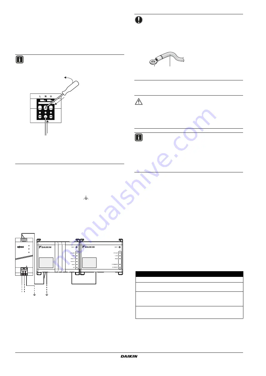
Connect the power supply to the three terminals, L (live),
N (neutral) and ground in the input section of the WAGO power
supply unit (PSU).
2
Connect the DC output of the WAGO PSU to the DC input of the
CPU module. Take the polarity of the wires into account.
3
Plug the A-type plug of the USB cable in the
rightmost
USB socket on the CPU module. This socket is marked "
I/O IF
".
4
Plug the B-type plug of the USB cable in the B-type USB socket
on the I/O module.
5
Provide an earth connection to the
terminal of the CPU
module, using one of the following two options:
connect the terminal to the earth rail bar of the electrical
cabinet (if provided), or
connect the terminal to the M3 earthing screw on the bottom
face of the WAGO PSU.
6
Once all wiring has been completed and double-checked, turn
on the power supply.
7.3.
Connecting the LAN cable
For all wiring requirements, refer to
"15.8. Wiring requirements" on
Do not connect the LAN cable until you start commissioning the
intelligent Tab Controller. Otherwise, a network address conflict may
occur.
8.
Installation of the Daikin-supplied
router
For information on the installation, refer to the manual provided with
the Daikin-supplied router. For information on when to use the
Daikin-supplied router, refer to
"4.4. Additional components in the
intelligent Tab Controller solution" on page 3
The following table gives an overview of the most relevant
information.
INFORMATION
Use a flat-head screwdriver to manipulate the WAGO PSU
cage clamp in such a way that the wires are fixed to the
power supply.
a
Place the screwdriver in the upper clamp entry
and place it above the clamp.
b
Push the clamp downwards by pivoting the
screwdriver in direction
'
b
'
, so that the lower
clamp entry opens.
c
Put the wire in the respective lower clamp
entry.
a
b
c
USB
230 V AC
POWER
I/O IF
CPU IF
24 V DC
+ + - -
L N
CPU
I/O
NOTICE
If you want to connect the earth wire to the WAGO PSU,
you can only use a stranded wire with a crimp-style
terminal on the tip of the wire.
Place the round crimp-style terminal on the wire up to the
insulated part and fasten the terminal with a Philips
screwdriver.
a
Round crimp-style terminal
b
Stranded conductor wire
CAUTION
The power supply is
only
guaranteed when the "DC OK"
LED on the WAGO PSU
and
the "CPU ALIVE" LEDs on
both
the CPU module and the I/O module are blinking.
If one or more of the above LEDs are not lighting up, check
for faulty wiring.
INFORMATION
A new CPU module does not come with application
software installed. Therefore, the "ALARM" LED will be lit
red. This is as expected, see
. Application software will
be installed during the commissioning phase, refer to
"9. Commissioning the intelligent Tab Controller setup" on
page 10
.
Requirement
Information
Default WiFi name (SSID)
ASUS
Default WiFi password (access
key)
To be found on the sticker at the back
of the router.
Router configuration URL
Use one of the following:
http://192.168.1.1
http://router.asus.com
Router configuration password
Not set. You will set this when you start
the router’s "Quick internet setup"
feature.
a
b


