background image

DCC601A51

intelligent Tab Controller

4P420109-1 – 2015.10

Installer reference guide

26

15.8. Wiring requirements

All wiring must comply with the following requirements:

16. Disposal requirements

The CPU module contains a replaceable battery, marked with the
following symbol:

This means that the battery may not be mixed with unsorted
household waste. If a chemical symbol is printed beneath the symbol,
this chemical symbol means that the battery contains a heavy metal
above a certain concentration.
Possible chemical symbols are: Pb: lead (>0.004%).
Waste batteries must be treated at a specialised treatment facility for
reuse. By ensuring waste batteries are disposed of correctly, you will
help to prevent potential negative consequences for the environment
and human health.

Both intelligent Tab Controller modules are marked with the following
symbol:

This means that electrical and electronic products may not be mixed
with unsorted household waste. Do NOT try to dismantle the system
yourself: the dismantling of the system, treatment of the refrigerant,
of oil and of other parts must be done by an authorised installer and
must comply with the applicable legislation.
Units must be treated at a specialised treatment facility for reuse,
recycling and recovery. By ensuring this product is disposed of
correctly, you will help to prevent potential negative consequences for
the environment and human health. For more information, contact
your installer or local authority.

17. Copyright and trademarks

SDHC Logo is a trademark of SD-3DC, LLC.

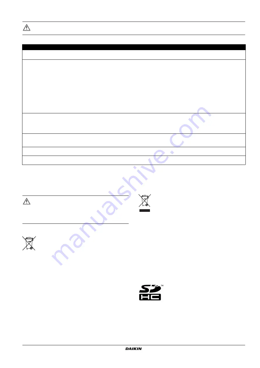
WARNING

Make sure all field wiring complies with the applicable legislation.

Connection

Cross section

Max. length

Remarks

LAN cable

100 m

UTP CAT 5e or higher

RJ-45 connector

DIII-NET (F1/F2)

Ø0.75~1.25 mm²

(terminal sized for maximum 

1.5 mm²)

Total length

(a)

: 2000 m (<1500 m 

when using shielded wire)

Max. length

(b)

: 1000 m

(a)

Total length

 is the sum of all wiring in the DIII-NET network.

(b)

Max. length

 is the maximum distance between any two connection points in the DIII-NET network.

Cable type: 2-core vinyl insulated vinyl-sheathed
cable/vinyl cabtyre cable or 2-core shielded cable

Do not use multicore cables with three or more cores

Do not use mixed cable types

Never bundle the cables

When using a shielded cable, connect only one end of
each shield wire to the ground

Make sure the wiring is routed and fixed, so as not to
touch unearthed accessible conductive parts

Make sure a strain relief is available for each wire
entering the electrical cabinet

Fore more information on DIII-NET, refer to the
D-BACS design guide (ED72-721)

Digital Inputs 
(Di1~Di4, Do)

Ø0.75~1.25 mm²

(terminal sized for maximum 

1.5 mm²)

200 m

The voltage-free contact connected to the input
terminal must be suitable for detection by 10 mA at
16 V DC

For pulse signals: pulse width 20~400 ms, pulse
interval: 100 ms or more

230 V AC power supply 
to the WAGO PSU

According to applicable legislation 

(terminal sized for maximum 

4 mm²)

According to applicable legislation

Solid or stranded wire allowed

The internal protection of the WAGO PSU is fused at
2.5 A  /  250 V

24 V DC power supply to 
the CPU module

According to applicable legislation

Solid or stranded wire allowed

USB cable

5 m

Commercial USB 2.0 cable, type-A to type-B connector 
(provided in the intelligent Tab Controller kit)

CAUTION

There is a risk of explosion if the internal battery is
replaced by an incorrect type.

Replace the battery according to the instructions in

"13. Replacing the data backup battery" on page 24

.

Summary of Contents for DCC601A51

Page 1: ...INSTALLER REFERENCE GUIDE DCC601A51 intelligent Tab Controller ...

Page 2: ...he connected devices local commissioning tool 13 9 8 Net commissioning 14 Operation 17 10 Advanced configuration of the intelligent Tab Controller 17 10 1 Local commissioning tool main window overview 17 10 2 Management points 17 10 3 Changing date and time 21 10 4 Changing network settings 22 10 5 Change the function mode 22 Maintenance 23 11 Setting equipment in and out of maintenance 23 12 Upgr...

Page 3: ...e equipment protective gloves safety glasses when installing maintaining or servicing the system WARNING Tear apart and throw away plastic packaging bags so that nobody especially children can play with them Possible risk suffocation DANGER RISK OF ELECTROCUTION Turn OFF all power supply before connecting electrical wiring or touching electrical parts Disconnect the power supply for more than 1 mi...

Page 4: ...nnect to certain Daikin units that provide a DIII NET communication interface The connection of Daikin equipment that uses other communication interfaces might be supported in future upgrades For an up to date list of which equipment can be controlled using the intelligent Tab Controller refer to the following site http www daikineurope com support and manuals product information In addition a num...

Page 5: ...it connected to DIII NET i Indoor unit connected to DIII NET j Forced stop contact input k Digital inputs can be configured as contact inputs or pulse inputs l Wired remote controller This is a conceptual wiring diagram for the correct wiring of the Di1 Di4 terminals refer to 7 1 2 Connecting digital input and output devices on page 8 USB 230 V AC RJ 45 F1 F2 P1 P2 F1 F2 P1 P2 F1 F2 P1 P2 F1 F2 OU...

Page 6: ...be opened only with a special tool The key or tool should be available only to service personnel must be installed in a space with no access for the general public must comply with the applicable legislation must have ingress protection class of IP4X or higher however make sure enough ventilation is provided to prevent overheating of the equipment must have impact protection class of IK07 or highe...

Page 7: ...ule k DIP SW Reserved for servicing Factory default all switches are set to off n BACKUP Switch for turning on off the backup power supply for retaining the current settings provided by the internal battery Factory default OFF This will be set to the ON position during commissioning q Lever To assist mounting dismounting the module onto from a DIN rail LEDs b CPU ALIVE Green This LED blinks when t...

Page 8: ...nks if a failure is detected For details on LED operations refer to the LED status and operation table I O module on page 7 d RS 485 Orange This LED blinks when data is being sent or received over the RS 485 port e P1P2 MONITOR Orange This LED blinks when data is being sent or received via the P1P2 line f DIII MONITOR Orange This LED blinks when DIII NET communication is performed LED status and o...

Page 9: ...wn in the following wiring diagram The function assignment however may be changed at a later time For more details on the required pulse width and interval refer to 15 8 Wiring requirements on page 26 For how to change the function assignment refer to 10 2 6 Management points attribute descriptions on page 19 Schematic wiring diagram with Di and Do terminals a Di1 Forced stop contact input normall...

Page 10: ...e 3 The following table gives an overview of the most relevant information INFORMATION Use a flat head screwdriver to manipulate the WAGO PSU cage clamp in such a way that the wires are fixed to the power supply a Place the screwdriver in the upper clamp entry and place it above the clamp b Push the clamp downwards by pivoting the screwdriver in direction b so that the lower clamp entry opens c Pu...

Page 11: ...P address and corresponding subnet mask the IP address of the default gateway the IP address of the DNS server and the IP address of the alternate DNS if applicable If you will connect the intelligent Tab Controller to your company WiFi contact your network administrator for the network name SSID and password authentication code If you want to use the cloud connect mode confirm with your network a...

Page 12: ...accept the terms of use 3 Enter the password default daikin 4 Make sure the IP address is 192 168 0 1 5 Click OK to log in 6 In the Execution Confirmation window make sure the version of the firmware that will be installed is newer than the Current version 7 Click Execute to confirm the upgrade The upgrade will be executed Wait until you get a confirmation that the firmware has been completely upg...

Page 13: ...to function in Stand alone Mode or Cloud connect Mode For more info on both modes refer to 4 System overview on page 3 9 If you want to use the intelligent Tab Controller app click Modify to set the authentication code for the app 10 Confirm all settings by clicking OK 9 6 Configuring the network settings local commissioning tool To let the intelligent Tab Controller function within your network y...

Page 14: ...uration of the connected devices local commissioning tool Before the intelligent Tab Controller can actually control any of the connected Daikin devices you will need to add them as so called management points For more info on management points refer to 10 2 Management points on page 17 To add devices as management points proceed as follows 1 Start the commissioning tool 2 Change the IP address to...

Page 15: ...ode Make sure all desired Daikin equipment is connected to the intelligent Tab Controller and the power is turned on Make sure to set an AirNet address for all indoor units and outdoor units and a DIII NET address for indoor units using a connected wired remote controller Make sure you have a list with all connected Daikin equipment with the following information Port and DIII NET address Model na...

Page 16: ...ted to 2 Select the desired DIII NET port 3 Click Outdoor Units The Outdoor Unit Setup window for this DIII NET address will be displayed 4 Enter the following data for this address if applicable available 5 Click the upper Apply button to confirm these changes 6 Select the desired outdoor unit from the list of outdoor units INFORMATION If you want to make changes to the configuration of your outd...

Page 17: ...ered information to the cloud To do so proceed as follows 1 In the net commissioning tool click Commissioning The net commissioning tool will automatically check if there is data to be transmitted 2 In the File Transmission window wait until File Transmission Completed is displayed If so click OK 3 If any information is missing the Check Missing Data window will display the reason why the file tra...

Page 18: ...Menu List a Service Settings b Mgmt Point Data Register c The Mgmt Point Data Register window will be displayed In this register you can do the following Register new management points automatically Refer to 10 2 3 Register management points automatically on page 18 Register new management points manually Refer to 10 2 4 Registering management points manually on page 18 Edit copy or delete managem...

Page 19: ... a management point select the desired management point and click Copy to make an exact copy of the selected management point Check for errors click Check to see if there aren t any errors in the management points register INFORMATION You can only perform these actions with the local commissioning tool The intelligent Tab Controller app does not allow you to register edit or delete management poin...

Page 20: ...entilation Mode Selecting ventilation mode will activate the Ventilator tab of this ventilation unit in the intelligent Tab Controller app If selected the Fresh Up and Auto Air Volume fields will be enabled Enable this option if you want to give the end user control over the ventilation mode of the connected ventilation units Fresh Up If selected Fresh Up operations will be added to Ventilation Am...

Page 21: ... the pulse amount default 1 1 The current pulse amount is retained 0 The pulse value is reset to 0 Any other value This specified pulse amount is applied Pulse Step The modifier that determines after how many pulses received by the attached equipment the pulse amount will be increased by 1 For example if the pulse step is set to 4 and 100 pulses are received the pulse amount will be set to 25 Clic...

Page 22: ...a Service Settings b Time Zone c 2 Select the desired Time Zone and confirm your selection 3 Click Menu List a System Settings b Time DST c 4 Click Modify to change the Date and Time setting 5 You can choose to Enable or Disable the Daylight Saving Time Settings 6 If enabled set the start and end date of summer time 7 Click OK to confirm all changes a b c a b c INFORMATION The newly set time will ...

Page 23: ...nd alone Mode or b Cloud connect Mode For more info on both modes refer to 4 System overview on page 3 3 If you want to use the intelligent Tab Controller app click Modify to set the authentication code for the app 4 Confirm all settings by clicking OK INFORMATION If any of the Network settings has been changed the CPU module will restart The commissioning tool will not automatically restart To co...

Page 24: ...m from this list 3 Confirm any changes with OK 12 Upgrading the firmware Daikin is constantly trying to improve your user experience To let the intelligent Tab Controller function as smoothly as possible please use the latest version of the firmware The latest version of both tools version up tool and commissioning tool is available on http www daikineurope com support and manuals software downloa...

Page 25: ...C Cool 18 32 C However it is possible to configure a set point outside these ranges using a wired remote controller In this case the intelligent Tab Controller will display the configured set point even if it falls outside the above limit values of the adapter Although fan settings can be configured using the intelligent Tab Controller the adapter does not support these operations Therefore any co...

Page 26: ...without condensation Item Specification Rated input voltage 110 240 V AC Input power frequency 50 60 Hz Power consumption CPU module I O module Max 13 W 11 W 2 W Typical 5 5 W 4 W 1 5 W Item Specification Internal battery type BR2032 3 V Internal battery estimated time typical that data remains stored with controller powered off 6 5 years Fuse CPU module and I O module Soldered into 250 V AC F2 5A...

Page 27: ...ax length Remarks LAN cable 100 m UTP CAT 5e or higher RJ 45 connector DIII NET F1 F2 Ø0 75 1 25 mm terminal sized for maximum 1 5 mm Total length a 2000 m 1500 m when using shielded wire Max length b 1000 m a Total length is the sum of all wiring in the DIII NET network b Max length is the maximum distance between any two connection points in the DIII NET network Cable type 2 core vinyl insulated...

Page 28: ...4P420109 1 2015 10 Copyright 2015 Daikin ...

Reviews: