


7 Installation
Installation manual
7
DCC601A51
intelligent Tablet Controller
4P414342-1D – 2020.12
B
k
l
m
Connectors
h
[DIII (F1/F2) and P1P2 (P1/P2)]
2×2 communication lines,
connecting the intelligent Tablet Controller with DIII-
compatible units and P1P2-compatible units respectively.
The P1P2 connection is reserved for future use.
i
[RS‑485]
Reserved for future use.
k
[CPU IF]
USB 2.0 type-B socket. To connect with the
CPU module. Acts as a power supply and communication
channel for the I/O module.
l
[Di1‑4 and Do]
Terminals for connecting digital inputs (Di)
and digital outputs (Do). The Do connection is reserved for
future use.
Controls and switches
a
[RESET]
Reserved for future use.
g
[DIII MASTER]
Switch for setting the intelligent Tablet
Controller to "MASTER" or "SLAVE" in a DIII-NET
configuration. Factory default: left position (MASTER).
j
[DIP SW]
Mode selector. Factory default: bit 1 is set to: "ON
(ON)"; bits 2-4 are set to: "OFF (OFF)".
m
[Lever]
To assist mounting/dismounting the module onto/
from a DIN rail.
LEDs
b
[CPU ALIVE]
(Green) This LED blinks when the I/O module
operates normally. For details on LED operations, refer to the
table below.
c
[ALARM]
(Red) This LED is lit or blinks if a failure is
detected. For details on LED operations, refer to the table
below.
d
[RS‑485]
(Orange) This LED blinks when data is being
sent or received over the RS‑485 port.
e
[P1P2 MONITOR]
(Orange) This LED blinks when data is
being sent or received via the P1P2 line.
f
[DIII MONITOR]
(Orange) This LED blinks when DIII-NET
communication is performed.
LED status and operation table (I/O module)
Operating condition
CPU ALIVE ALARM
Normal
Blink
OFF
Hardware failure
OFF
ON
Power interruption
OFF
OFF
Communication failure between CPU
module and I/O module (for 10 seconds
or more)
ON
Blink
7
Installation
7.1
Installation of the intelligent Tablet
Controller hardware
The intelligent Tablet Controller components are to be mounted onto
a 35 mm DIN rail, inside an electrical cabinet. For more information
see
"6.3.1 About installation place and mounting direction"
5].
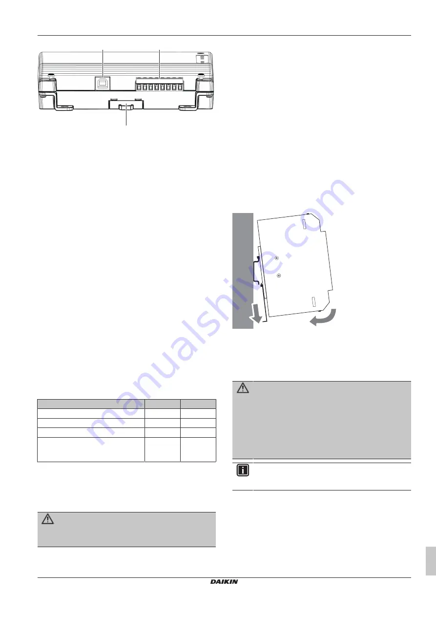
7.1.1
To install the 3 intelligent Tablet
Controller hardware components
1
Place the module over the top of the DIN-35 rail so that the
upper hook on the rear face is hooked in.
2
Push the module in direction 'a' until the lower hook snaps into
the rail.
3
If necessary, pull the lever on the lower parts of the module in
direction 'b' to click the module onto the rail. Use a flat-blade
screwdriver if necessary.
4
Repeat the previous steps for all other modules.
b
a
7.2
About electric wiring
This chapter will describe the procedure to connect the intelligent
Tablet Controller kit components with Daikin devices and other
equipment.
WARNING
▪ Do NOT turn on the power supply before all wire
connections are completed. Not doing so may cause an
electric shock.
▪ After the wiring is completed, double-check that all
wires are connected correctly before turning on the
power supply.
▪ All field supplied parts, materials and electric works
MUST comply with the applicable legislation.
INFORMATION
At the time of writing, some connectors are NOT active, but
provided for future use.
7.2.1
Wiring requirements
WARNING
All field wiring and components MUST be installed by a
licensed electrician and MUST comply with the applicable
legislation.
All wiring must comply with the following requirements:


