12
2nd Stage Cooling Mode Sequence:
On a call for 2nd stage cooling, the Y2 or Y2 and G thermo
-
stat contacts close signaling the furnace control board with
24 VAC on Y2 or Y2 and G terminals.
•
The 7-Segment will display the cool mode:
•
The compressor and condenser fan are energized.
•
The circulator fan is energized at cool speed after a
cool on delay. The electronic air cleaner will also be
energized.
•
After the thermostat is satisfied, the compressor
is de-energized and the Cool Mode Fan Off Delay
period begins.
•
Following the Cool Mode Fan Off Delay period, the
cool circulator and air cleaner relay are de-energized
Cooling Mode Speed Selection
To change the main blower speed in COOLING mode, follow
the following steps:
1.
Press the left or right switch until LED displays “AC1
“(for single stage COOLING) or “AC2 “(for two-stage
COOLING). Press the center switch and LED will dis-
play the selected speed number as Fxx (xx: Blower
speed number from 1 to 9).
2. The control will rotate available speed number every
time left/right switches are pressed. All 9 speeds are
available for both Single and Two Stage cooling.
3.
When the center switch is pressed, the current dis
-
played speed will be selected, and control will apply
the newly selected speed in next cooling call.
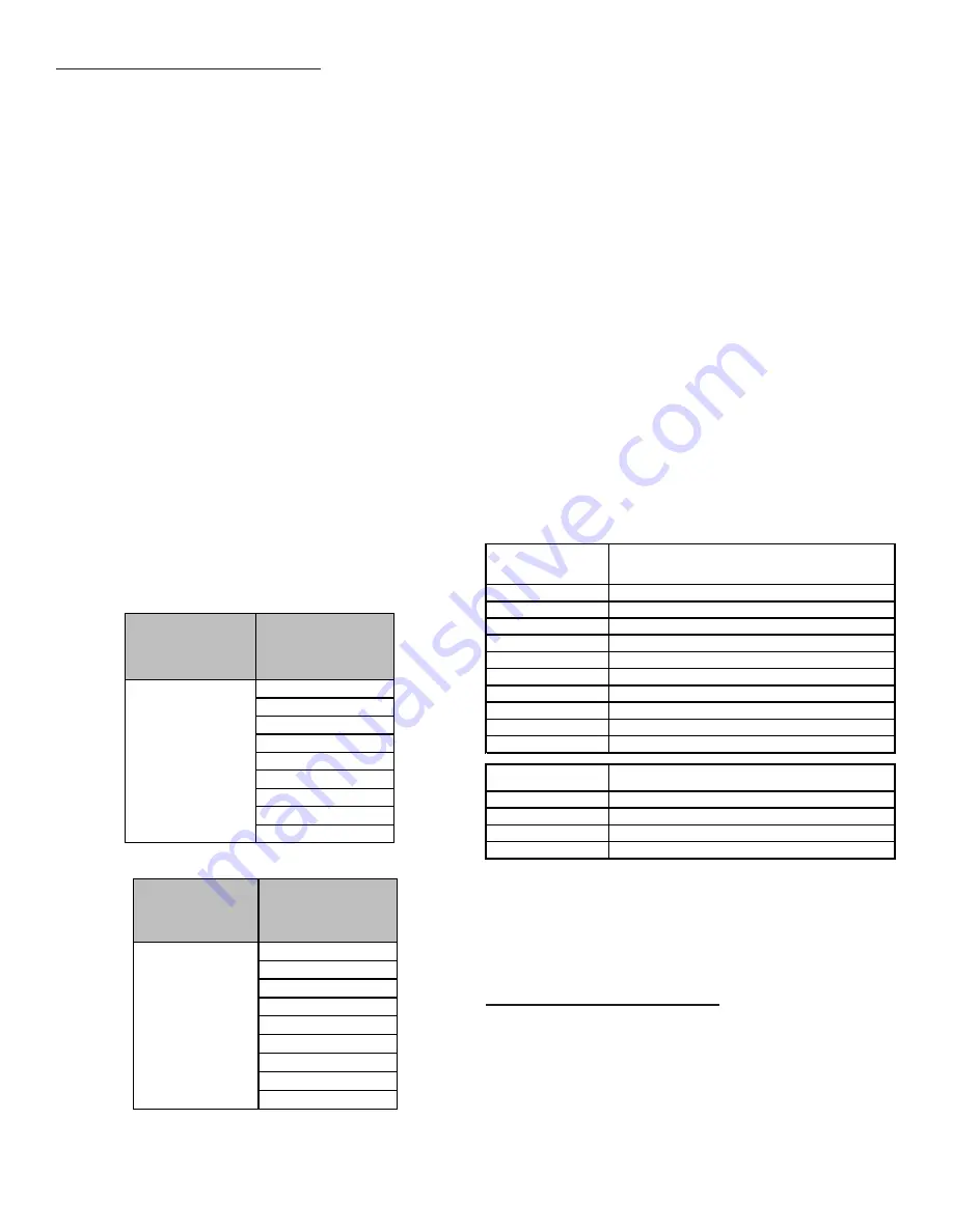
THERMOSTAT
CALL
AVAILABLE
SPEEDS
Y/Y1
F01
F02
F03
F04
(DEFAULT)
F05
F06
F07
F08
F09
Single-Stage Cooling Speed Table for 2 Stage IFC
THERMOSTAT
CALL
AVAILABLE
SPEEDS
Y2
F01
F02
F03
F04
F05
(DEFAULT)
F06
F07
F08
F09
Two-Stage Cooling Speed Table for 2 Stage IFC
Furnace Shutdown
1. Set the thermostat to the lowest setting. The inte-
grated control will close the gas valve and extinguish
flame. Following a 15 second delay, the induced draft
blower will be de-energized. After the blower off delay
time expires, the blower de-energizes.
2. Remove the burner compartment door and move the
furnace gas valve manual control to the OFF position.
3.
Close the manual gas shutoff valve external to the
furnace.
4. Replace the burner compartment door.
Filters
Filters must be used and well maintained. There are no pro-
visions to install filters inside the furnace cabinet. Refer to
the chart below for minimum filter sizes. A deep pleated filter
or electronic air filter may also be used.
DM80SN Models
DM80SN furnaces require installer provision of a return air
filter located on the side or bottom of the furnace or a cen
-
trally located filter.
DC80SN Models
DC80SN furnaces require installer provision of a filter rack
located in the return air plenum or a centrally located filter
Upflow / Horizontal
Models
Minimum Recommended Filter Size^
*0403A*
1 - 16 X 25 Side or 1 - 14 X 24 Bottom Return
*0603A*
1 - 16 X 25 Side or 1 - 14 X 24 Bottom Return
*0604B*
1 - 16 X 25 Side or Bottom Return
*0803B*
1 - 16 X 25 Side or Bottom Return
*0804B*
1 - 16 X 25 Side or Bottom Return
*0805C*
1 - 16 X 25 Side or Bottom Return¹
*0805D*
2 - 16 X 25 Side or 1 - 20 X 25 Bottom Return
*1005C*
2 - 16 X 25 Side or 1 - 20 X 25 Bottom Return
*1205D*
2 - 16 X 25 Side or 1 - 24 X 24 Bottom Return
*1405D*
2 - 16 X 25 Side or 1 - 24 X 24 Bottom Return
Downflow Models
Minimum Recommended Filter Size^
*0403A*
2 - 10 X 20 or 1 - 14 X 25 Top Return
*0603A*
2 - 10 X 20 or 1 - 14 X 25 Top Return
*0804B*
2 - 14 X 20 or 1 - 16 X 25 Top Return
*1005C*
2 - 14 X 20 or 1 - 20 X 25 Top Return
¹ = us e 2 - 16 X 25 fi l ters a nd two s i de returns or 20 X 25 fi l ter on bottom
return i f furna ce i s connected to a cool i ng uni t over 4 tons nomi na l ca pa ci ty
^ Fi l ters ma y a l s o be centra l l y l oca ted
Additional Filtering Accessories
External Filter Rack Kit (EFR01)
The external filter rack kit is intended to provide a location
external to the furnace casing, for installation of a perma
-
nent filter on upflow model furnaces. The rack is designed
to mount over the indoor blower compartment area of either
side panel, and provide filter retention as well as a location
for attaching return air ductwork.


