2 Components
Service manual
18
ATXP20~3 FTXP20~7 ARXP20~3
RXP20~71L2V1B
Split Comfora R32
ESIE18-01 – 2019.02
2
Components
2.1
4-way valve
2.1.1
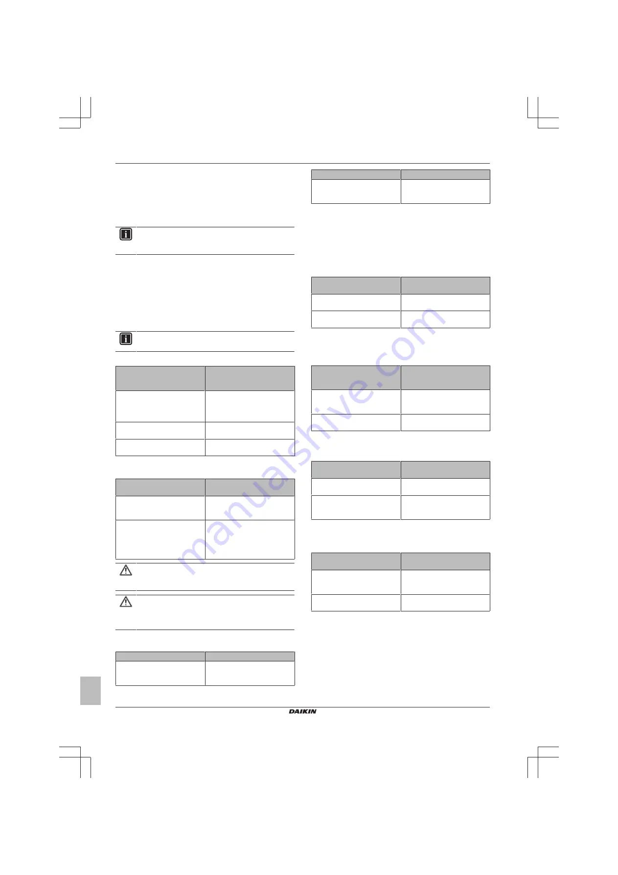
Checking procedures
INFORMATION
It is recommended to perform the checks in the listed
order.
To perform a mechanical check of the 4-way valve
Prerequisite:
Turn OFF the unit via the user interface.
Prerequisite:
Turn OFF the respective circuit breaker.
Prerequisite:
Remove the required plate work, see
1
Disconnect the 4‑way valve connector from the main PCB.
2
Turn ON the power of the unit.
INFORMATION
Default position of the 4‑way valve is Heating mode.
3
Activate Heating operation via the user interface.
Water temperature after plate
type heat exchanger of the
indoor unit:
Action
Drops
4‑way valve is stuck in cooling
position. Replace the 4‑way
valve body, see
Rises
Skip the next step of this
procedure.
Does NOT rise/drop
Perform the next step of this
procedure.
4
Connect a manifold to one of the service ports of the refrigerant
circuit and check the pressure.
Refrigerant pressure
measured?
Action
Yes
Perform a position check of the
4‑way valve, see
No
Leaks may be found in the
refrigerant circuit. Perform a
pressure test of the refrigerant
circuit, see
CAUTION
To prevent damage due to liquid entering the compressor,
the steps below MUST ONLY be executed once.
CAUTION
Make sure you have a pressure difference of at least 6 bar
between the high and low pressure when performing this
test.
5
Place a round permanent magnet on the core of the solenoid
valve and listen to the 4‑way valve.
Does the 4‑way valve switch?
Action
Yes
Perform an electrical check of the
4‑way valve, see
Does the 4‑way valve switch?
Action
No
Replace the 4‑way valve body,
see
.
To perform an electrical check of the 4-way valve
1
First perform a mechanical check of the 4‑way valve, see
"2.1.1 Checking procedures" on page 18
2
Activate Cooling operation via the user interface.
3
Measure the voltage on the 4‑way valve connector pins 1-3.
The measured voltage MUST be 220~240 V AC during
switching and 12 V DC after switching of the 4‑way valve.
Is the measured voltage
correct?
Action
Yes
Skip the next step of this
procedure.
No
Perform the next step of this
procedure.
4
Disconnect the 4‑way valve connector from the main PCB and
measure the voltage on the connector pins 1-3 of the connector
on the main PCB. The voltage MUST be 220~240 V AC during
switching and 12 V DC after switching.
Is the measured voltage on the
4‑way valve connector of the
main PCB correct?
Action
Yes
Replace the 4‑way valve coil, see
"2.1.2 Repair procedures" on
page 19
.
No
Replace the main PCB, see
5
Disconnect the 4‑way valve connector from the main PCB and
measure the resistance of the 4‑way valve coil. The resistance
MUST be 1000~2000 Ω.
Is the measured resistance
correct?
Action
Yes
Perform the next step of this
procedure.
No
Replace the 4‑way valve coil, see
"2.1.2 Repair procedures" on
page 19
.
6
De-activate Cooling and activate Heating operation via the user
interface.
7
Measure the temperature after the plate type heat exchanger.
Does the measured
temperature rise?
Action
Yes
Perform a position check of the
4‑way valve, see
No
Replace the main PCB, see
To perform a position check of the 4-way valve
1
First perform a mechanical check of the 4‑way valve, see
"2.1.1 Checking procedures" on page 18
2
Slide a magnet over the front and rear side of the 4‑way valve
body. The magnet MUST be attracted in the positions a or b,
but NOT in positions c.


