IM 817-7
68 www.DaikinApplied.com
The “DraftStop” system can be employed even in those
marginal applications to provide the occupants comfort
without the material installation and operating cost
penalty associated with “auxiliary radiation.” The unit
ventilator is ordered with the return air intake having a
draftstop blockoff to restrict return air flow through the
front bottom unit opening, option “30” in field “11” of the
model number. This allows drawing of return air through
the draftstop enclosure located under the windows. A
manually adjustable damper is located beneath each
section of DraftStop grille, see
. This damper
is provided so that a uniform air velocity can be achieved
throughout the entire length of the DraftStop grille. This
simple adjustment is made once by the installer during
the final stage of installation.
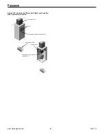
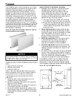
Figure 127: Typical Finned Radiation Enclosure (left) And
Typical DraftStop Enclosure (right)
NOTICE
The following information is a general outline for installing the
Draftstop system. Refer to the specific installation instructions
provided with the Draftstop system equipment.
Draftstop is made up of three separate sections as listed
below:
1 .
Upper channel or backplate
2 .
Mounting components
3 .
Enclosures and trims
Items 1, and 2 are materials which will be required to
start the installation. Item 3 is the completion material
and should be stored in a safe area until needed.
The following step-by-step procedures should be
adhered to:
1 .
Check the area in which the equipment is to be
installed and clear away the debris.
2 .
Review the engineered floor plans or the approved
equipment room schedule.
3 .
Place the proper amount of equipment in each area
in accordance with plans or schedule.
4 .
Proceed to install the equipment as outlined on the
following pages. Refer to the installation instructions
included with the Draftstop system for more detailed
information.
Upper Channel or Backplate Assembly
1 .
Establish a level chalk line on the wall at a height
specified for the top of the enclosure. Select
mounting hardware which is suitable for the type
of wall construction used and mount the upper
channel or backplate flush with the chalk line. When
mounting, use the prepunched holes and push the
hardware through the sponge gasket.
a .
The upper channel is provided with continuous
5/16" diameter holes on 2" centers for mounting.
b .
Where used, the backplate assembly consists of
a full backplate welded to the back of the upper
channel. Fasten the backplate at the bottom as
well as at the top.
2 .
Wall-to-Wall Application:
Starting at the left side,
run the upper channel or backplate along the wall.
Note that the upper channel or backplate is installed
behind the wall trim as well as the enclosure,
because both the enclosure and wall trim rest in the
top groove of the upper channel.
3 .
Wall-to-End Application:
Run the upper channel
or backplate from the wall to a point where the
enclosure will end. See Draftstop installation
instructions for details of end cap installation.
4 .
End-to-End Application:
Run the upper channel
or backplate the same length as the enclosure. See
Draftstop installation instructions for details or end
cap installation.
5 .
For inside corners, run the upper channel or backplate
into the corner, butting the pieces together. If desired,
pieces may be stopped short of the corner a maximum
of one inch. Refer to the Draftstop installation
instructions for details of the corner trim installation.
The Draftstop enclosure and unit ventilator end panel
should be matched, to ensure proper airflow.
show the various end panels available,
follow installation instructions included with the end panels.
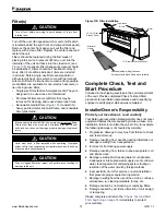
Figure 128: Typical DraftStop Enclosure
Piping Area
5
3
⁄
8
"
3
1
⁄
8
"
12"
(305mm),
20"
(508mm)
& 24"
(610mm)
Floor
Mounting
Channel Detail
Open
3
⁄
8
" (10mm)
Max. Screw
(By Others)
1
1
⁄
4
"
(32mm)
2"
(51mm)
Enclosure
Slide
Closed

