background image

11

English

Refrigerant Piping Work

2.

Refrigerant piping.

CAUTION

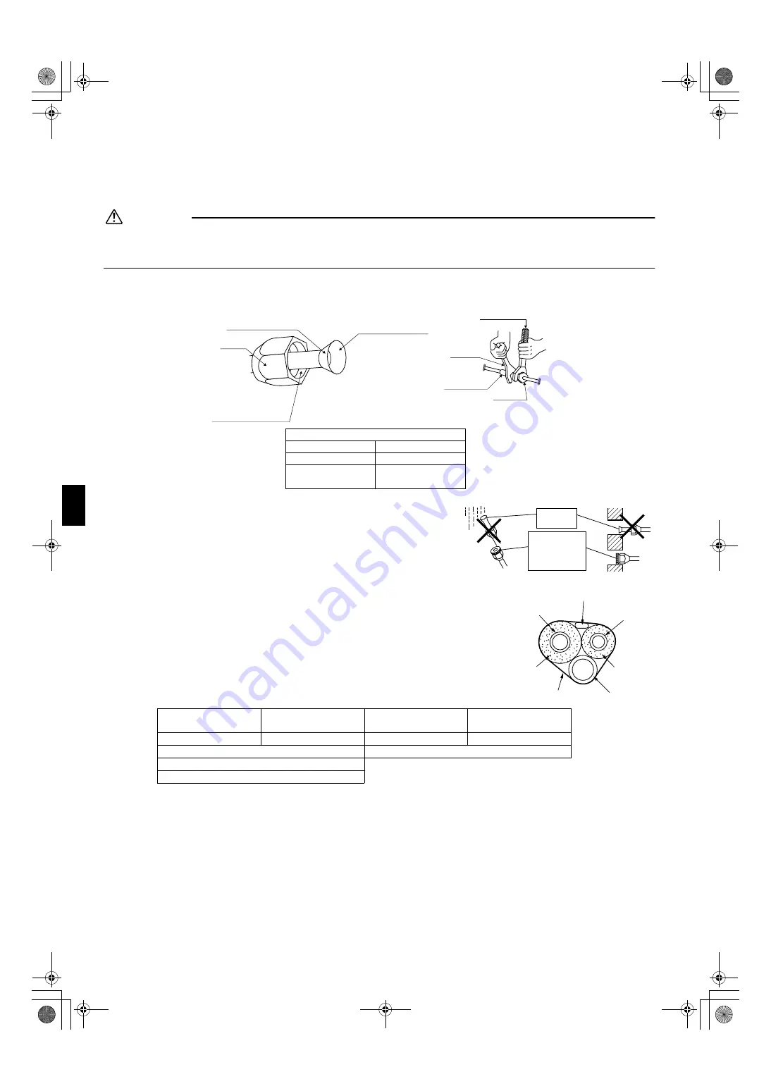
1) Use the flare nut fixed to the main unit. (To prevent cracking of the flare nut by aged deterioration.)
2) To prevent gas leakage, apply refrigeration oil only to the inner surface of the flare. (Use refrigeration oil for R410A.)
3) Use torque wrenches when tightening the flare nuts to prevent damage to the flare nuts and gas leakage.

Align the centres of both flares and tighten the flare nuts 3 or 4 turns by hand.  Then tighten them fully with the torque wrenches. 

2-1. Caution on piping handling. 

1) Protect the open end of the pipe against dust and moisture.
2) All pipe bends should be as gentle as possible. Use a pipe bender 

for bending. 

2-2. Selection of copper and heat insulation materials.

• When using commercial copper pipes and fittings, observe the following:
1) Insulation material:  Polyethylene foam

Heat transfer rate:  0.041 to 0.052W/mK (0.035 to 0.045 kcal/(mh•°C))
Refrigerant gas pipe’s surface temperature reaches 110°C max.
Choose heat insulation materials that will withstand this temperature.

2) Be sure to insulate both the gas and liquid piping and to provide insulation dimen-

sions as below.

3) Use separate thermal insulation pipes for gas and liquid refrigerant pipes.

Gas side

Liquid side

Gas pipe thermal 

insulation

Liquid pipe thermal 

insulation

O.D. 9.5mm

O.D. 6.4mm

I.D. 12-15mm

I.D. 8-10mm

Minimum bend radius

Thickness 10mm Min.

30mm or more

Thickness 0.8mm (C1220T-O)

Do not apply refrigeration 

oil to the outer surface.

Flare nut

Apply refrigeration oil to 

the inner surface of the 

flare.

Do not apply refrigeration 

oil to the flare nut avoid 

tightening with over torque.

[Apply oil]

Torque wrench

Piping union

Flare nut

Spanner

[Tighten]

Flare nut tightening torque

Gas side

Liquid side

3/8 inch

1/4 inch

32.7-39.9N 

l

 m

(330-407kgf 

l

 cm)

14.2-17.2N 

l

 m

(144-175kgf 

l

 cm)


Gas pipe

Liquid pipe

Gas pipe 
insulation

Liquid pipe 
insulation

Finishing tape

Drain hose

Inter-unit wiring

01_EN_3P207973-1D.fm  Page 11  Friday, September 4, 2009  10:44 AM

Summary of Contents for ATX20GV1B

Page 1: ...s Montaj kýlavuzlarý R410A Split serisi Installationsanleitung Split Baureihe R410A Manuel d installation Série split R410A Montagehandleiding R410A Split systeem Manual de instalación Serie Split R410A Manuale d installazione Serie Multiambienti R410A Εγχειρßδιο εγκατÜστασηò διαιροýìενηò σειρÜò R410A Manual de Instalação Série split R410A Рóêоводство по монтажó Серия R410A с раздельной óстановêой...

Page 2: ...FTK25GV1B FTK35GV1B FTX20JV1B FTX25JV1B FTX35JV1B DAIKIN INDUSTRIES LTD Shinri Sada Manager Quality Control Department 11th of Sep 2009 Low Voltage 2006 95 EC Electromagnetic Compatibility 2004 108 EC DAIKIN TCF 015 M12 09 2009 KEMA Quality B V 74736 KRQ EMC97 4957 3SB64526 1D fm Page 1 Tuesday September 15 2009 11 52 AM ...

Page 3: ...clamping may cause terminal overheating or fire After connecting interconnecting and supply wiring be sure to shape the cables so that they do not put undue force on the electrical covers or panels Install covers over the wires Incomplete cover installation may cause terminal overheating electrical shock or fire If any refrigerant has leaked out during the installation work ventilate the room The ...

Page 4: ...ectronic ignition type fluorescent lamps inverter or rapid start type as they may shorten the remote control range 8 the unit is at least 1 metre away from any television or radio set unit may cause interference with the picture or sound 9 install at the recommended height 1 8m 2 Wireless remote controller 1 Turn on all the fluorescent lamps in the room if any and find the site where remote contro...

Page 5: ... When there is no work space because the unit is close to ceiling CAUTION Be sure to wear protection gloves Place both hands under the center of the front grille and while pushing up pull it toward you Installation method 1 Install the front grille and firmly engage the upper hooks 3 locations 2 Install 2screws of the front grille 3 Install the air filter and then mount the front panel 3 How to se...

Page 6: ...ipe hole gap with putty Mounting plate Clip Mark rear side Bottom frame Front grille How to attach the indoor unit Hook the claws of the bottom frame to the mounting plate If the claws are difficult to hook remove the front grille How to remove the indoor unit Push up the marked area at the lower part of the front grille to release the claws If it is difficult to release remove the front grille Th...

Page 7: ...nting plate retention spots and Dimensions 770 Use tape measure as shown Position the end of a tape measure at Keep here the piece cut out from the unit for piping Liquid pipe end Gas pipe end The removed pipe port cover can be kept in the mounting plate pocket Removed pipe port cover A Mounting plate Through the wall hole φ65mm Recommended mounting plate retention spots 5 spots in all Place a lev...

Page 8: ... pipes and drain hose together with an insulation tape 3 Pass the drain hose and refrigerant pipes through the wall hole then set the indoor unit on the mounting plate hooks by using the markings at the top of the indoor unit as a guide 4 Open the front panel then open the service lid Refer to Installation tips 5 Pass the interconnecting wires from the outdoor unit through the feed through wall ho...

Page 9: ...move the drain hose 2 Reattach the insulation fixing screw on the right as it was Forgetting to attach this may cause water leakages 3 Remove the drain plug on the left side and attach it to the right side 4 Insert the drain hose and tighten with included indoor unit fixing screw How to replace the drain plug and drain hose Drain hose attachment position The drain hose is on the back of the unit F...

Page 10: ...an be performed with the electrical component box attached Omit the steps involved with removing and installing the electrical component box in order to perform the work more efficiently 5 1 Remove the front grille 2 screws 5 2 Remove the service lid 1 screw 5 3 Remove the cover from the indoor unit electrical component box Figure 1 5 4 Remove the indoor unit electrical component box 1 Remove the ...

Page 11: ...component box 2 Route the connection cord as shown in Figure 3 5 8 Install the indoor unit electrical component box in its original position 1 Install the flap 2 Install the electrical component box 1 screw 3 Install the thermistor in its original position on the heat exchanger 4 Install the connector S200 in its original position 5 Connect the communication wiring in its original position 5 9 Ins...

Page 12: ...nt mineral oil from getting into the system as this would reduce the lifetime of the units 3 Never use piping which has been used for previous installations Only use parts which are delivered with the unit 4 Do never install a drier to this R410A unit in order to guarantee its lifetime 5 The drying material may dissolve and damage the system 6 Incomplete flaring may cause refrigerant gas leakage T...

Page 13: ...0 035 to 0 045 kcal mh C Refrigerant gas pipe s surface temperature reaches 110 C max Choose heat insulation materials that will withstand this temperature 2 Be sure to insulate both the gas and liquid piping and to provide insulation dimen sions as below 3 Use separate thermal insulation pipes for gas and liquid refrigerant pipes Gas side Liquid side Gas pipe thermal insulation Liquid pipe therma...

Page 14: ...a small amount of power in its standby mode If the system is not to be used for some time after installation shut off the circuit breaker to eliminate unnecessary power consumption If the circuit breaker trips to shut off the power to the air conditioner the system will restore the original operation mode when the circuit breaker is opened again 2 Test items Test items Symptom diagnostic display o...

Page 15: ... 0911 HT 3P207973 1D M07B030C Two dimensional bar code is a code for manufacturing 00_CV_3P207973 1D fm Page 2 Friday September 4 2009 10 41 AM ...

Reviews: