background image

6 Installation

Installer reference guide

14

ARXM25~3RXM20~35N2V1B9

R32 split series

4P518023-5C – 2018.09

a

b

a

Cut exactly at right angles.

b

Remove burrs.

3

Remove  the  flare  nut  from  the  stop  valve  and  put  the  flare  nut
on the pipe.

4

Flare  the  pipe.  Set  exactly  at  the  position  as  shown  in  the
following figure.

A

Flare tool for R32

(clutch type)

Conventional flare tool

Clutch type

(Ridgid-type)

Wing nut type

(Imperial-type)

A

0~0.5 mm

1.0~1.5 mm

1.5~2.0 mm

5

Check that the flaring is properly made.

a

b

c

a

Flare’s inner surface MUST be flawless.

b

The pipe end MUST be evenly flared in a perfect circle.

c

Make sure the flare nut is fitted.

6.4.6

Using the stop valve and service port

CAUTION

Do  NOT  open  the  valves  before  flaring  is  complete.  This
would cause refrigerant gas leakage.

To handle the stop valve

Take the following guidelines into account:

▪ The stop valves are factory closed.

▪ The  following  figure  shows  the  stop  valve  parts  required  when

handling the valve.

c
d

a

b

a

Service port and service port cap

b

Valve stem

c

Field piping connection

d

Stem cap

▪ Keep both stop valves open during operation.

▪ Do  NOT  apply  excessive  force  to  the  valve  stem.  Doing  so  may

break the valve body.

▪ ALWAYS make sure to secure the stop valve with a spanner, then

loosen or tighten the flare nut with a torque wrench. Do NOT place
the  spanner  on  the  stem  cap,  as  this  could  cause  a  refrigerant
leak.

a

b

a

Spanner

b

Torque wrench

▪ When  it  is  expected  that  the  operating  pressure  will  be  low  (e.g.

when  cooling  will  be  performed  while  the  outside  air  temperature
is  low),  sufficiently  seal  the  flare  nut  in  the  stop  valve  on  the  gas
line with silicon sealant to prevent freezing.

Silicon sealant; make sure there is no gap.

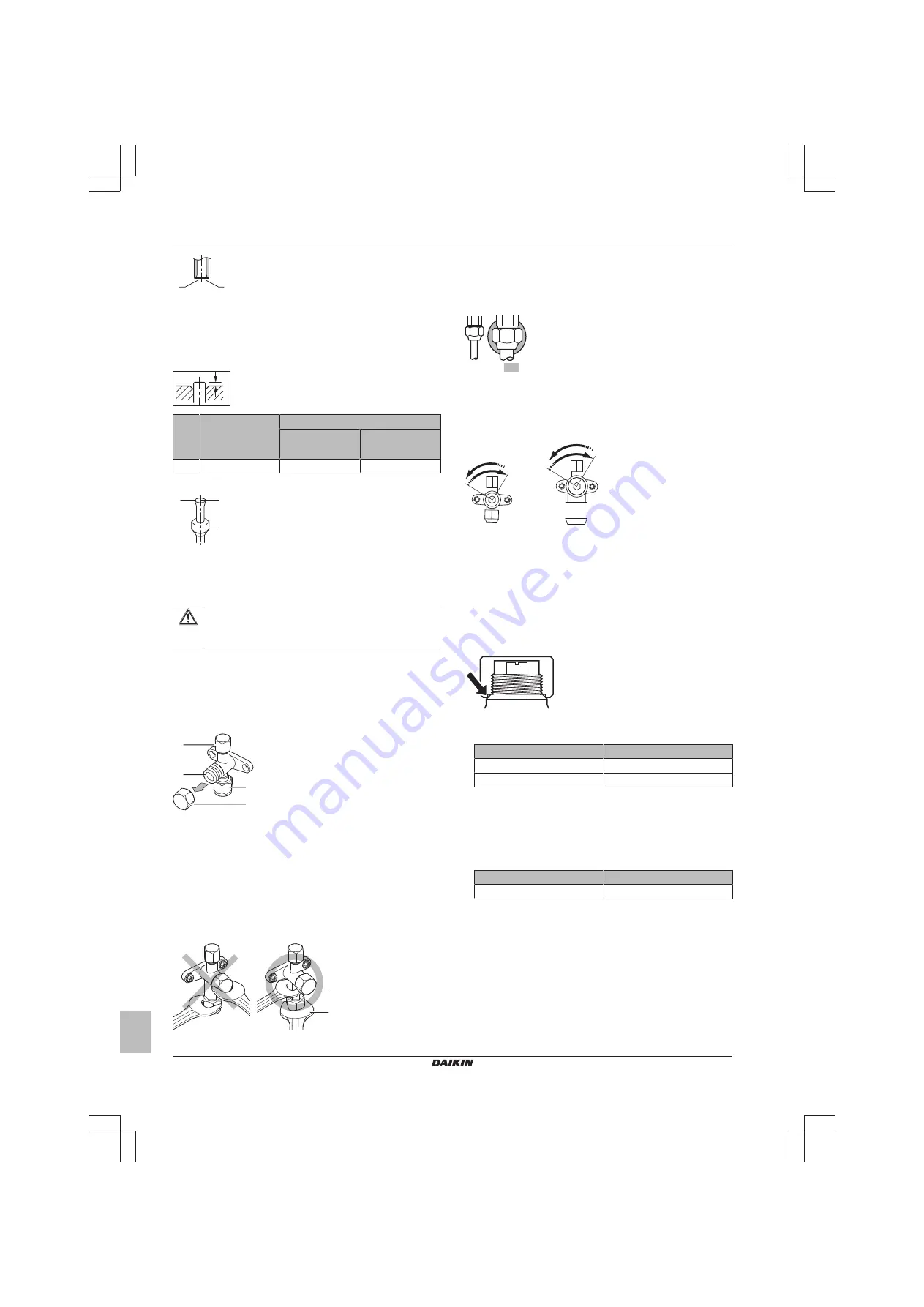
To open/close the stop valve

1

Remove the stop valve cover.

2

Insert  a  hexagon  wrench  (liquid  side:  4  mm,  gas  side:  4  mm)
into the valve stem and turn the valve stem:

Counterclockwise to open.
Clockwise to close.

3

When  the  stop  valve  CANNOT  be  turned  any  further,  stop
turning.

4

Install the stop valve cover.

Result: 

The valve is now open/closed.

To handle the stem cap

▪ The  stem  cap  is  sealed  where  indicated  with  the  arrow.  Do  NOT

damage it.

▪ After handling the stop valve, tighten the stem cap, and check for

refrigerant leaks.

Item

Tightening torque (N∙m)

Stem cap, liquid side

14.2~17.2

Stem cap, gas side

17.1~20.9

To handle the service cap

▪ ALWAYS use a charge hose equipped with a valve depressor pin,

since the service port is a Schrader type valve.

▪ After  handling  the  service  port,  tighten  the  service  port  cap,  and

check for refrigerant leaks.

Item

Tightening torque (N∙m)

Service port cap

10.8~14.7

6.4.7

To connect the refrigerant piping to the
outdoor unit

Piping length.

 Keep field piping as short as possible.

Piping  protection.

  Protect  the  field  piping  against  physical

damage.

1

Connect the liquid refrigerant connection from the indoor unit to
the liquid stop valve of the outdoor unit.

Summary of Contents for ARXM25N2V1B9

Page 1: ...Installer reference guide R32 split series English Installer reference guide R32 split series ARXM25N2V1B9 ARXM35N2V1B9 RXM20N2V1B9 RXM25N2V1B9 RXM35N2V1B9 ...

Page 2: ...3 To check for leaks 15 6 5 4 To perform vacuum drying 15 6 6 Charging refrigerant 16 6 6 1 About charging refrigerant 16 6 6 2 About the refrigerant 16 6 6 3 Precautions when charging refrigerant 16 6 6 4 To determine the additional refrigerant amount 16 6 6 5 To determine the complete recharge amount 17 6 6 6 To charge additional refrigerant 17 6 6 7 To fix the fluorinated greenhouse gases label...

Page 3: ...fety glasses when installing maintaining or servicing the system WARNING Tear apart and throw away plastic packaging bags so that nobody especially children can play with them Possible risk suffocation DANGER RISK OF BURNING Do NOT touch the refrigerant piping water piping or internal parts during and immediately after operation It could be too hot or too cold Give it time to return to normal temp...

Page 4: ...f pipework shall be kept to a minimum WARNING If appliances contain R32 refrigerant the floor area of the room in which the appliances are installed operated and stored MUST be larger than the minimum floor area defined in table below A m2 This applies to Indoor units without a refrigerant leakage sensor in case of indoor units with refrigerant leakage sensor consult the installation manual Outdoo...

Page 5: ...ntilate the area immediately Possible risks Excessive refrigerant concentrations in a closed room can lead to oxygen deficiency Toxic gas may be produced if refrigerant gas comes into contact with fire DANGER RISK OF EXPLOSION Pump down Refrigerant leakage If you want to pump down the system and there is a leak in the refrigerant circuit Do NOT use the unit s automatic pump down function with whic...

Page 6: ...g WARNING ONLY use copper wires Make sure the field wiring complies with the applicable legislation All field wiring MUST be performed in accordance with the wiring diagram supplied with the product NEVER squeeze bundled cables and make sure they do NOT come in contact with the piping and sharp edges Make sure no external pressure is applied to the terminal connections Make sure to install earth w...

Page 7: ...ical data is available on the regional Daikin website publicly accessible The full set of latest technical data is available on the Daikin extranet authentication required 2 2 Installer reference guide at a glance Chapter Description General safety precautions Safety instructions that you MUST read before installing About the documentation What documentation exists for the installer About the box ...

Page 8: ... 1 Overview About the unit This chapter contains information about Identification of the outdoor unit 4 2 Identification NOTICE When installing or servicing several units at the same time make sure NOT to switch the service panels between different models 4 2 1 Identification label Outdoor unit Location 5 Preparation 5 1 Overview Preparation This chapter describes what you have to do and know befo...

Page 9: ...ir inlet NOTICE The height of the wall on the outlet side of the outdoor unit MUST be 1200 mm NOTICE Do NOT stack the units on each other Do NOT hang the unit on a ceiling Strong winds 18 km h blowing against the outdoor unit s air outlet causes short circuit suction of discharge air This may result in deterioration of the operational capacity frequent frost acceleration in heating operation disru...

Page 10: ...ssible make sure that the heat exchanger coil is NOT affected by the snow If necessary install a snow cover or shed and a pedestal 5 2 3 Refrigerant piping length and height difference What Distance Maximum allowable pipe length 20 m Minimum allowable pipe length 1 5 m Maximum allowable height difference 15 m 5 3 Preparing refrigerant piping 5 3 1 Refrigerant piping requirements INFORMATION Also r...

Page 11: ... you have to do and know on site to install the system Typical workflow Installation typically consists of the following stages 1 Opening the unit 2 Mounting the outdoor unit 3 Connecting the refrigerant piping 4 Checking the refrigerant piping 5 Charging refrigerant 6 Connecting the electrical wiring 7 Finishing the outdoor unit installation 6 2 Opening the unit 6 2 1 About opening the unit At ce...

Page 12: ...f the unit in order to prevent water from getting into the unit and to avoid drain water dripping see the following figure NOTICE If the unit is installed in a cold climate take adequate measures so that the evacuated condensate CANNOT freeze INFORMATION For information on the available options contact your dealer NOTICE Provide at least 300 mm of free space below the unit Additionally make sure t...

Page 13: ...tection method Outdoor unit 1 month Pinch the pipe 1 month Pinch or tape the pipe Indoor unit Regardless of the period INFORMATION Do NOT open the refrigerant stop valve before checking the refrigerant piping When you need to charge additional refrigerant it is recommended to open the refrigerant stop valve after charging WARNING Connect the refrigerant piping securely before running the compresso...

Page 14: ... stem cap as this could cause a refrigerant leak a b a Spanner b Torque wrench When it is expected that the operating pressure will be low e g when cooling will be performed while the outside air temperature is low sufficiently seal the flare nut in the stop valve on the gas line with silicon sealant to prevent freezing Silicon sealant make sure there is no gap To open close the stop valve 1 Remov...

Page 15: ... same pump for other refrigerants may damage the pump and the unit NOTICE Connect the vacuum pump to the service port of the gas stop valve Make sure that the gas stop valve and liquid stop valve are firmly closed before performing the leak test or vacuum drying 6 5 3 To check for leaks NOTICE Do NOT exceed the unit s maximum working pressure see PS High on the unit name plate NOTICE Make sure to ...

Page 16: ... on the outdoor unit s internal refrigerant piping is performed NOTICE Before completely recharging perform vacuum drying on the outdoor unit s internal refrigerant piping as well Typical workflow Completely recharging refrigerant typically consists of the following stages 1 Determining how much refrigerant to charge 2 Charging refrigerant 3 Filling in the fluorinated greenhouse gases label and fi...

Page 17: ...m expressed as tonnes CO2 equivalent is used to determine the maintenance intervals Follow the applicable legislation Formula to calculate the greenhouse gas emissions GWP value of the refrigerant Total refrigerant charge in kg 1000 2 Fix the label on the inside of the outdoor unit near the gas and liquid stop valves 6 7 Connecting the electrical wiring 6 7 1 About connecting the electrical wiring...

Page 18: ...single core wire b Screw c Flat washer Stranded conductor wire with round crimp style terminal c b b a c a B B a Terminal b Screw c Flat washer O Allowed X NOT allowed Tightening torques Item Tightening torque N m M4 X1M 1 5 1 6 M4 earth 1 4 1 5 If single core wires are used be sure to curl the end of the lead Improper work may cause heat or fire The earth wire between the wire retainer and the te...

Page 19: ...s of the following stages 1 Checking the Checklist before commissioning 2 Performing a test run for the system 7 2 Precautions when commissioning DANGER RISK OF ELECTROCUTION DANGER RISK OF BURNING CAUTION Do NOT perform the test operation while working on the indoor units When performing the test operation NOT only the outdoor unit but the connected indoor unit will operate as well Working on an ...

Page 20: ...city When the power turns back on after a power break the previously selected mode will be resumed 7 6 Starting up the outdoor unit See the indoor unit installation manual for configuration and commissioning of the system 8 Configuration 8 1 Facility setting Use this function for cooling at low outdoor temperature This function is designed for facilities such as equipment of computer rooms NEVER u...

Page 21: ...scribes what you have to do in case of problems It contains information about solving problems based on symptoms Before troubleshooting Carry out a thorough visual inspection of the unit and look for obvious defects such as loose connections or defective wiring 11 2 Precautions when troubleshooting WARNING When carrying out an inspection on the switch box of the unit ALWAYS make sure that the unit...

Page 22: ...u want to pump down the system and there is a leak in the refrigerant circuit Do NOT use the unit s automatic pump down function with which you can collect all refrigerant from the system into the outdoor unit Possible consequence Self combustion and explosion of the compressor because of air going into the operating compressor Use a separate recovery system so that the unit s compressor does NOT ...

Page 23: ...r the procedure refer to To perform a test run in the installation manual of the indoor unit Note Forced cooling will stop automatically after around 30 minutes 2 To stop operation sooner press the ON OFF switch INFORMATION If forced cooling is used and the outside temperature is 10 C the safety device may prevent operation Warm the outside temperature thermistor on the outdoor unit to 10 C Result...

Page 24: ...H E H HEATER F U FU FOR CHARACTERISTICS FUSE REFER TO PCB INSIDE YOUR UNIT FG CONNECTOR FRAME GROUND H HARNESS H P LED V L PILOT LAMP LIGHT EMITTING DIODE HAP LIGHT EMITTING DIODE SERVICE MONITOR GREEN HIGH VOLTAGE HIGH VOLTAGE IES INTELLIGENT EYE SENSOR IPM INTELLIGENT POWER MODULE K R KCR KFR KHuR K M MAGNETIC RELAY L LIVE L COIL L R REACTOR M STEPPER MOTOR M C COMPRESSOR MOTOR M F FAN MOTOR M P...

Page 25: ... or application explaining how to install configure and maintain it Operation manual Instruction manual specified for a certain product or application explaining how to operate it Maintenance instructions Instruction manual specified for a certain product or application which explains if relevant how to install configure operate and or maintain the product or application Accessories Labels manuals...

Page 26: ......

Page 27: ......

Page 28: ...4P518023 5C 2018 09 Copyright 2018 Daikin ...

Reviews: