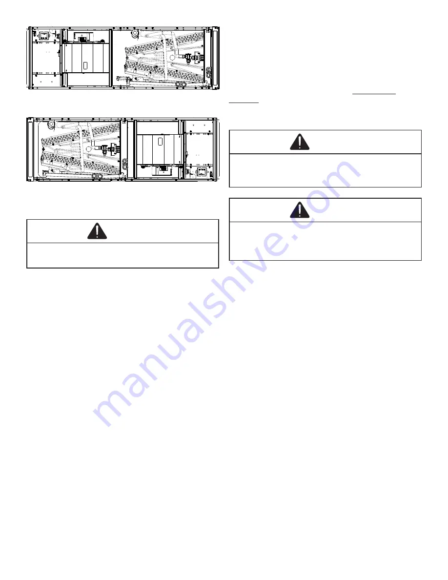
background image

7

HORIZONTAL LEFT

Figure 5

HORIZONTAL RIGHT

Figure 6

7  Refrigerant Lines

WARNING

This product is factory-shipped with R410A and dry nitrogen 

mixture gas under pressure. Use appropriate service tools 

and follow these instructions to prevent injury.

NOTE: Refrigerant tubing must be routed to allow 

adequate access for servicing and maintenance of the 

unit.

Do not install the air handler in a location that violates 

the instructions provided with the condenser. If the unit 

is located in an unconditioned area with high ambient 

temperature and/or high humidity, the air handler may be 

subject to nuisance sweating of the air handler cabinet. On 

these installations, a wrap of 2” fiberglass insulation with a 

vapor barrier is recommended. 

7.1 Tubing Size

For the correct tubing size, follow the specification for the 

condenser/heat pump.

7.2 Tubing Preparation

All cut ends are to be round, burr free, and clean.  Failure 

to follow this practice increases the chances for refrigerant 

leaks. The suction line is spun closed and requires tubing 

cutters to remove the closed end.

NOTE: To prevent possible damage to the tubing joints, 

do not handle coil assembly with manifold or flowrator 

tubes. Always use clean gloves when handling coil 

assemblies.

NOTE: The use of a heat shield is strongly 

recommended when brazing  to avoid burning the 

serial plate or the finish of the unit. 

Heat trap or 

wet rags must be used to protect heat sensitive 

components such as service valves and TXV valves 

sensing bulb.

WARNING

A quenching cloth is strongly recommended to prevent 

scorching or marring of the equipment finish when brazing 

close to the painted surfaces. Use brazing alloy of 5% 

minimum silver content.

CAUTION

Applying too much heat to any tube can melt the tube. 

Torch heat required to braze tubes of various sizes must be 

proportional to the size of the tube. Service personnel must 

use the appropriate heat level for the size of the tube being 

brazed.

7.3 Tubing Connections

An adjustable TXV with bulb is installed on the vapor tube 

from the factory.

1.  Remove refrigerant tubing panel or coil (lower) access 

panel.  

2. 

Remove access valve fitting cap and depress the 

valve stem in access fitting to release pressure. No 

pressure indicates possible leak.

3.  Replace the panel.

4.  Remove the spin closure on both the liquid and 

suction tubes using a tubing cutter.

5.  Insert liquid line set into liquid tube expansion and 

slide grommet about 18” away from braze joint. 

6.  Insert suction line set into suction tube expansion and 

slide insulation and grommet about 18” away from 

braze joint. 

7.  Braze joints. Quench all brazed joints with water or a 

wet rag upon completion of brazing.

Summary of Contents for AMST U1400 Series

Page 1: ...ice Inspection 12 12 2 Wire Sizing 12 12 3 Maximum Overcurrent Protection MOP 12 12 4 Electrical Connections Supply Voltage 13 12 4 1 Air Handler Only Non Heat Kit Models 13 12 4 2 Air Handler Non Cir...

Page 2: ...d the danger of CO poisoning which can occur if a carbon monoxide producing device con nues to operate in the enclosed area Carbon monoxide emissions can be re circulated throughout the structure if t...

Page 3: ...Shipping Material Removal IMPORTANT All Shipping Material used to protect the equipment and the equipment s components during transit should be removed before final installation 2 3 1 Blower Support...

Page 4: ...stall units such that a positive slope in condensate line 1 4 per foot is allowed 5 5 Horizontal Applications If installed above a finished living space a secondary drain pan as required by many build...

Page 5: ...LUG KIT Table 1 SIDE DRAIN PAN DPK1 DRAIN PLUG COIL ACCESS PANEL MAIN DRAIN PAN Drain Pan Figure 1 1 Side Drain Pan Removal Figure 2 6 2 Horizontal Left Installation Figure 5 No field modifications ar...

Page 6: ...available through your local distributor The kits are not supplied with the air handler and must be used to assist with condensation management in humid environment applications The individual instal...

Page 7: ...ssemblies NOTE The use of a heat shield is strongly recommended when brazing to avoid burning the serial plate or the finish of the unit Heat trap or wet rags must be used to protect heat sensitive co...

Page 8: ...ng Panel Internal Part Terminology Figure 7 External Part Terminology Figure 8 Coil Installation For Downflow Figure 9 Access Panel Configuration for Downflow or Horizontal Right Figure 10 Important N...

Page 9: ...d superheat of 8 F 1 F If subcooling and superheat are low adjust TXV to 8 F 1 F superheat then check subcooling a If subcooling is low and superheat is high add charge to raise subcooling to 8 F 1 F...

Page 10: ...ttention CAUTION If secondary drain is not installed the secondary access must be plugged Insulate drain lines located inside the building or above a finished living space to prevent sweating Install...

Page 11: ...dimension must be less than 23 x20 filter can be installed on a B C and D cabinet respectively the cabinet size is the seventh letter of the model number 11 Electric Heat Refer to the installation man...

Page 12: ...In Canada electrical grounding is to be in accordance with the Canadian Electric Code CSA C22 1 12 1 Building Electrical Service Inspection This unit is designed for single phase electrical supply onl...

Page 13: ...C approved strain relief is to be used at this entry point Some codes municipalities require the supply wire to be enclosed in conduit Consult your local codes Side of Cabinet Top of Cabinet KNOCK OUT...

Page 14: ...tdoor section is single stage or two stage The 24V control voltage connects the air handler to the room thermostat and condenser Low voltage wiring must be copper conductors A minimum of 18AWG must be...

Page 15: ...BK T1 T3 Tap 8 BK PU BK T1 T4 Tap 9 BK PU BK T1 T5 Table 13 Speed Taps 6 9 Wiring Figure 14 12 6 3 AMST60DU1400 ONLY For high static applications no speed tap or airflow modifications should be made f...

Page 16: ...tened All panels must be in place and secured For Air Tight application gasket must be positioned at prescribed locations to achieve 1 4 leakage Tubing must be leak free Condensate line must be trappe...

Page 17: ...95 625 615 515 T9 995 970 925 910 860 850 800 790 730 T1 750 725 670 655 585 570 465 455 360 T2 920 895 845 830 780 770 710 700 615 T3 985 960 915 900 850 840 785 775 710 T4 1185 1165 1125 1115 1070 1...

Page 18: ...T2 1580 1550 1490 1470 1400 1390 1315 1305 1230 T3 1635 1610 1560 1545 1480 1470 1400 1390 1315 T4 1851 1810 1768 1733 1704 1662 1613 1486 1358 T5 1820 1795 1750 1735 1680 1670 1605 1595 1525 T6 1465...

Page 19: ...the connections between room thermostat and the air handlers and the connections between the air handlers and the Condensing Unit or Heat Pump with optional connections to Outdoor Thermostats For eac...

Page 20: ...UNIT 24V CONNECTION BL YL YL WH GR RD 18 GA 4 WIRES WITH COOLING 3 WIRES WITHOUT AIR HANDLER Y G W W2 R COOLING UNIT WITH OPTIONAL HEAT KITS OF 15 kW AND ABOVE AND ROOM THERMOSTAT WITH TWO STAGES OF H...

Page 21: ...EMOVE WIRE WHEN USING OUTDOOR THERMOSTAT NOMENCLATURE OT OUTDOOR THERMOSTAT OPTIONAL EHR EMERGENCY HEAT RELAY OPTIONAL COLOR CODES RD RED YL YELLOW BL BLUE BR BROWN OR ORANGE WH WHITE G C R HEAT PUMP...

Page 22: ...PLUG CONNECTOR TRANSFORMER HIGH VOLTAGE LOW VOLTAGE HIGH VOLTAGE LOW VOLTAGE PLF 2 COLOR CODE TR 6 5 PLM 4 4 24V 5 1 2 3 EM WIRING CODE 208 240 VOLTS 1 1 PLF PLM L1 PLM 2 L2 IF REPLACEMENT OF THE ORI...

Page 23: ...AGE HIGH VOLTAGE LOW VOLTAGE PLF 2 COLOR CODE TR 6 5 PLM 4 4 24V 5 1 2 3 EM WIRING CODE 208 240 VOLTS 1 1 PLF PLM L1 PLM 2 L2 IF REPLACEMENT OF THE ORIGINAL WIRES SUPPLIED WITH THIS ASSEMBLY IS NECESS...

Page 24: ...am on the unit for the most up to date wiring 3 Phase Heat Kit 18 Wiring Diagrams HIGH VOLTAGE DISCONNECT ALL POWER BEFORE SERVICING OR INSTALLING THIS UNIT MULTIPLE POWER SOURCES MAY BE PRESENT FAILU...

Page 25: ...icals can cause premature aluminum evaporator coil failure Any cleaners that contain corrosive chemicals including but not limited to chlorine and hydroxides should not be used An alternate cleaning m...

Page 26: ...WB F DB F WB F Heating Supply Air Temperature DB F Temperature Rise DB F Delta T Difference between Supply and Return Temperatures DB F AirHandler Coil InverterMatched INVERTERAH COILONLY Check EEV an...

Page 27: ...27 THIS PAGE IS INTENTIONALLY LEFT BLANK...

Page 28: ...REGISTRATION Thank you for your recent purchase Though not required to get the protection of the standard warranty registering your product is a relatively short process and entitles you to additional...

Reviews: