Installer reference guide
Daikin Altherma – Low temperature split
English
+
ERLQ004-006-008CAEHVH/X04S18CBEHVH/26CB
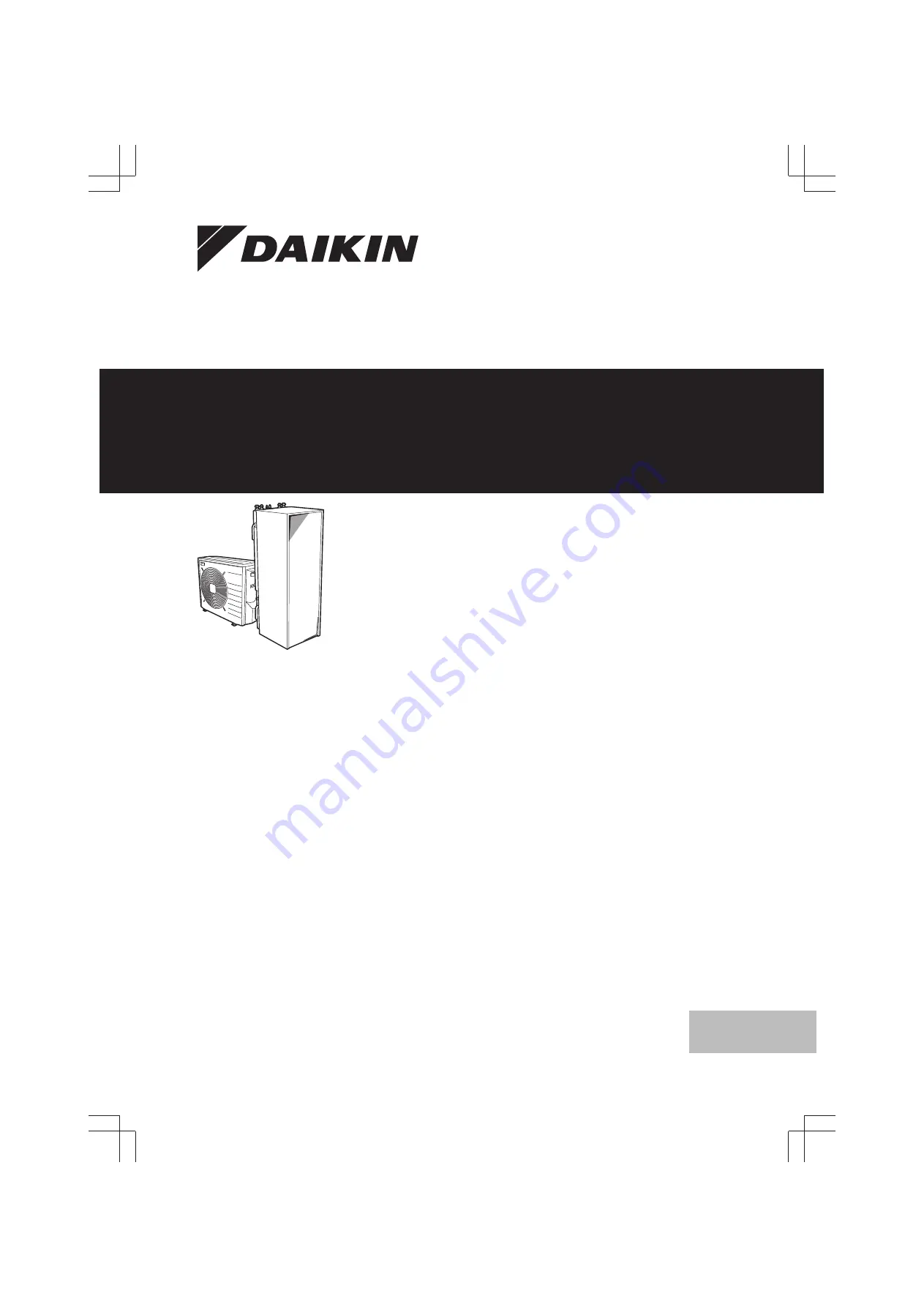
Page 1: ...Installer reference guide Daikin Altherma Low temperature split English Installer reference guide Daikin Altherma Low temperature split ERLQ004 006 008CA EHVH X04S18CB EHVH X08S18 26CB ...
Page 2: ...er circuit requirements 24 6 4 2 Formula to calculate the expansion vessel pre pressure 25 6 4 3 To check the water volume and flow rate 26 6 4 4 Changing the pre pressure of the expansion vessel 26 6 4 5 To check the water volume Examples 27 6 5 Preparing electrical wiring 27 6 5 1 About preparing electrical wiring 27 6 5 2 About preferential kWh rate power supply 27 6 5 3 Overview of electrical ...
Page 3: ... the user 76 11 Maintenance and service 76 11 1 Overview Maintenance and service 77 11 2 Maintenance safety precautions 77 11 2 1 Opening the indoor unit 77 11 3 Checklist for yearly maintenance of the outdoor unit 77 11 4 Checklist for yearly maintenance of the indoor unit 77 11 4 1 To drain the domestic hot water tank 78 12 Troubleshooting 78 12 1 Overview Troubleshooting 78 12 2 Precautions whe...
Page 4: ...that the unit can be used as a shelter by small animals Small animals that make contact with electrical parts can cause malfunctions smoke or fire CAUTION Do NOT touch the air inlet or aluminum fins of the unit NOTICE Do NOT place any objects or equipment on top of the unit Do NOT sit climb or stand on the unit NOTICE Works executed on the outdoor unit are best done under dry weather conditions to...
Page 5: ...n refrigerant cylinders slowly Charge the refrigerant in liquid form Adding it in gas form may prevent normal operation CAUTION When the refrigerant charging procedure is done or when pausing close the valve of the refrigerant tank immediately If the valve is not closed immediately remaining pressure might charge additional refrigerant Possible consequence Incorrect refrigerant amount 1 2 4 Brine ...
Page 6: ...f the power supply is three phase and the compressor has an ON OFF starting method If there exists the possibility of reversed phase after a momentary black out and the power goes on and off while the product is operating attach a reversed phase protection circuit locally Running the product in reversed phase can break the compressor and other parts 2 About the documentation 2 1 About this documen...
Page 7: ...to do after the boxes with the outdoor and indoor unit are delivered on site It contains information about Unpacking and handling the units Removing the accessories from the units Keep the following in mind At delivery the unit must be checked for damage Any damage must be reported immediately to the carrier s claims agent Bring the packed unit as close as possible to its final installation positi...
Page 8: ...t Watch your fingers there are sharp edges on the lower part of the front plate a e h g f 5 4 1 2 3 4 4 2 6 Remove the accessories 1 1 1 1 1 2 1 2 a b c d f g e h a General safety precautions b Addendum book for optional equipment c Indoor unit installation manual d Operation manual e Sealing ring for shut off valve f Shut off valve g User interface cover h 2 screws for fixing the user interface 7...
Page 9: ... required to avoid freezing up of the drain pan It is recommended to install this option in colder regions with possible low ambient temperatures or heavy snowfall For installation instructions see the installation manual of the drain pan heater INFORMATION In case the drain pan heater is used the jumper JP_DP on the service PCB on the outdoor unit MUST be cut After cutting the jumper you MUST res...
Page 10: ... For installation instructions see the installation manual of the demand PCB and addendum book for optional equipment Remote indoor sensor KRCS01 1 By default the internal user interface sensor will be used as room temperature sensor As an option the remote indoor sensor can be installed to measure the room temperature on another location For installation instructions see the installation manual o...
Page 11: ... frost protection is only possible if the leaving water temperature control on the unit s user interface is turned ON INFORMATION In case an external room thermostat is used and room frost protection needs to be guaranteed in all conditions then you have to set auto emergency A 5 1 2 to 1 5 2 1 Single room Under floor heating or radiators Wired room thermostat Setup B A a A Main leaving water temp...
Page 12: ...the heat pump convectors The under floor heating or radiators are directly connected to the indoor unit The desired room temperature is set via the remote controller of the heat pump convectors The space heating cooling demand signal is sent to one digital input on the indoor unit X2M 1 and X2M 4 The space operation mode is sent to the heat pump convectors by one digital output on the indoor unit ...
Page 13: ...ater temperature of all heat emitters is the same you do NOT need a mixing valve station cost effective Example If the heat pump system is used to heat up one floor where all the rooms have the same heat emitters Under floor heating or radiators Thermostatic valves If you are heating up rooms with under floor heating or radiators a very common way is to control the temperature of the main room by ...
Page 14: ...ndoor unit will only supply leaving water temperature when there is an actual demand INFORMATION To increase comfort and performance Daikin recommends to install the valve kit option EKVKHPC on each heat pump convector Configuration Setting Value Unit temperature control A 2 1 7 Code C 07 1 Ext RT control Unit operation is decided by the external thermostat Number of water temperature zones A 2 1 ...
Page 15: ...f both water temperature zones For the main zone A mixing valve station is installed before the under floor heating The pump of the mixing valve station is controlled by the ON OFF signal on the indoor unit X2M 5 and X2M 7 normal closed shut off valve output The room temperature is controlled by the user interface which is used as room thermostat For the additional zone The heat pump convectors ar...
Page 16: ...rned OFF Bivalent operation is only possible for space heating NOT for domestic hot water production Domestic hot water is always produced by the DHW tank connected to the indoor unit INFORMATION During heating operation of the heat pump the heat pump operates to achieve the desired temperature set via the user interface When weather dependent operation is active the water temperature is determine...
Page 17: ...or temperature thermostat An electricity tariff contact A manually operated contact Setup Connect the following field wiring L N H Com A K2A K1A X2M BTI K2A K1A Indoor Auto Boiler 1 2 3 4 X Y Indoor BTI Boiler thermostat input A Auxiliary contact normal closed H Heating demand room thermostat optional K1A Auxiliary relay for activation of indoor unit field supply K2A Auxiliary relay for activation...
Page 18: ... is needed at the kitchen sink per day 1 sink 2 min 5 l min 10 l Are there any other domestic hot water needs Example If the DHW consumption of a family 4 persons per day is as follows 3 showers 1 bath 3 sink volumes Then the DHW consumption 3 100 l 1 150 l 3 10 l 480 l Determining the volume and desired temperature for the DHW tank Formula Example V1 V2 V2 T2 40 40 T1 If V2 180 l T2 54 C T1 15 C ...
Page 19: ...ter temperature The flow rate The power consumption of the booster heater if applicable in the domestic hot water tank Setup and configuration No additional equipment needed Only in case a booster heater is present in the system measure its capacity resistance measurement and set the capacity via the user interface Example If you measure a booster heater resistance of 17 1Ω the capacity of the hea...
Page 20: ...onsumption You only need to set the number of pulses of each power meter See 5 5 4 Preferential kWh rate power supply on page 20 for an example with two power meters 5 5 4 Preferential kWh rate power supply General rule Power meter 1 Measures the outdoor unit Power meter 2 Measures the rest i e indoor unit backup heater and optional booster heater Setup Connect power meter 1 to X5M 7 and X5M 8 Con...
Page 21: ...e lighting domestic appliances space heating a b c A B C D 1 2 3 4 5 A8P A Outdoor unit B Indoor unit C DHW tank D Energy management system a Power limitation activation 4 digital inputs b Backup heater c Booster heater Pi t DI4 DI3 DI1 a b Pi Power input t Time DI Digital inputs power limitation levels a Power limitation active b Actual power input Setup Demand PCB option EKRP1AHTA needed Maximum...
Page 22: ...e 46 the outdoor unit is turned down to reduce the standby energy losses As a result the outdoor ambient temperature is NOT read out If the desired leaving water temperature is weather dependent the full time outdoor temperature measurement is important This is another reason to install the optional outdoor ambient temperature sensor INFORMATION The external outdoor ambient sensor data either aver...
Page 23: ...inds This is to prevent corrosion caused by high levels of salt in the air which might shorten the life of the unit Install the outdoor unit away from direct sea winds Example Behind the building b c a If the outdoor unit is exposed to direct sea winds install a windbreaker Height of windbreaker 1 5 height of outdoor unit Mind the service space requirements when installing the windbreaker a b c d ...
Page 24: ... 045 kcal mh C with a heat resistance of at least 120 C Insulation thickness Pipe outer diameter Øp Insulation inner diameter Øi Insulation thickness t 6 4 mm 1 4 8 10 mm 10 mm 15 9 mm 5 8 16 20 mm 13 mm Øi Øi t Øp Øp If the temperature is higher than 30 C and the humidity is higher than RH 80 the thickness of the insulation materials should be at least 20 mm to prevent condensation on the surface...
Page 25: ...ping insulate the brass and non brass properly so that they do NOT make contact with each other This to prevent galvanic corrosion Valve Separating circuits When using a 3 way valve in the water circuit make sure that the domestic hot water circuit and the floor heating circuit is fully separated Valve Change over time When using a 2 way valve or a 3 way valve in the water circuit the maximum chan...
Page 26: ...e following Decrease the pre pressure Check if the water volume does NOT exceed the maximum allowed water volume 7 m Do the following Increase the pre pressure Check if the water volume does NOT exceed the maximum allowed water volume The expansion vessel of the indoor unit is too small for the installation In this case it is recommended to install an extra vessel outside the unit a This is the he...
Page 27: ... system They can cause overheating electrical shock or fire Do NOT install a phase advancing capacitor because this unit is equipped with an inverter A phase advancing capacitor will reduce performance and may cause accidents WARNING All wiring must be performed by an authorized electrician and must comply with the applicable legislation Make electrical connections to the fixed wiring All componen...
Page 28: ...15 20 12 6 13 17 18 a Indoor unit Item Description Wires Maximum running current Outdoor unit and indoor unit power supply 1 Power supply for outdoor unit 2 GND or 3 GND a 2 Power supply and interconnection cable to indoor unit 3 c Item Description Wires Maximum running current 3 Power supply for backup heater See table below 4 Preferential kWh rate power supply voltage free contact 2 d 5 Normal k...
Page 29: ...ROCUTION DANGER RISK OF BURNING 1 1 2 2 7 2 3 To open the indoor unit 1 Loosen and remove the screws at the bottom of the unit 2 Push on the button at the bottom of the front plate WARNING Sharp edges Take the front plate on the upper part instead of the lower part Watch your fingers there are sharp edges on the lower part of the front plate 3 Slide the front panel of the unit downwards and remove...
Page 30: ...hers field supply as follows INFORMATION The maximum height of the upper protruding part of the bolts is 15 mm NOTICE Fix the outdoor unit to the foundation bolts using nuts with resin washers a If the coating on the fastening area is stripped off the nuts rust easily a 283 5 8 0 1 0 0 mm 1 0 0 300 In any case provide at least 300 mm of free space below the unit Additionally make sure the unit is ...
Page 31: ...in pan cause damage to the location Make sure that condensation water can be evacuated properly Install the unit on a base to make sure that there is a proper drainage in order to avoid ice accumulation Prepare a water drainage channel around the foundation to drain waste water surrounding the unit Avoid drain water flowing over the footpath so that it does not become slippery in case of ambient f...
Page 32: ...You have to mount the outdoor and indoor unit before you can connect the refrigerant and water piping Typical workflow Mounting the indoor unit typically consists of the following stages 1 Installing the indoor unit 7 4 2 Precautions when mounting the indoor unit INFORMATION Also read the precautions and requirements in the following chapters General safety precautions Preparation 7 4 3 To install...
Page 33: ...walls see figure below Unit Installation period Protection method Outdoor unit 1 month Pinch the pipe 1 month Pinch or tape the pipe Indoor unit Regardless of the period INFORMATION Do NOT open the refrigerant stop valve before checking the refrigerant piping When you need to charge additional refrigerant it is recommended to open the refrigerant stop valve after charging 7 5 3 Guidelines when con...
Page 34: ... systems For instance if chlorine based flux is used it will cause pipe corrosion or in particular if the flux contains fluorine it will deteriorate the refrigerant oil 7 5 7 Using the stop valve and service port To handle the stop valve Take the following guidelines into account The stop valves are factory closed The following illustration shows each part required in handling the valve c d a b a ...
Page 35: ...ting or the refrigerant piping is wrapped with finishing tape 7 6 Checking the refrigerant piping 7 6 1 About checking the refrigerant piping The outdoor unit s internal refrigerant piping has been factory tested for leaks You only have to check the outdoor unit s external refrigerant piping Before checking the refrigerant piping Make sure the refrigerant piping is connected between the outdoor un...
Page 36: ...n the vacuum for 1 hour do the following Check for leaks again Perform vacuum drying again NOTICE Be sure to open the gas stop valve after piping installation and vacuuming Running the system with the valve closed the compressor may break down 7 7 Charging refrigerant 7 7 1 About charging refrigerant The outdoor unit is factory charged with refrigerant but in some cases the following might be nece...
Page 37: ...el off the applicable language and stick it on top of a b Factory refrigerant charge see unit name plate c Additional refrigerant amount charged d Total refrigerant charge e Greenhouse gas emissions of the total refrigerant charge expressed as tonnes CO2 equivalent f GWP Global warming potential NOTICE In Europe the greenhouse gas emissions of the total refrigerant charge in the system expressed a...
Page 38: ... Also the field installation piping tapping points etc connected to the tank is subjected to this high pressure To prevent this a pressure relieve valve needs to be installed The overpressure prevention depends on the correct operation of the field installed pressure relief valve If this is NOT working correctly overpressure will deform the tank and water leakage may occur To confirm good operatio...
Page 39: ...g the electrical wiring Before connecting the electrical wiring Make sure The refrigerant piping is connected and checked The water piping is connected Typical workflow Connecting the electrical wiring typically consists of the following stages 1 Making sure the power supply system complies with the electrical specifications of the heat pump 2 Connecting the electrical wiring to the outdoor unit 3...
Page 40: ...r 2 1 2 3 Strip insulation 20 mm from the wires a b a Strip wire end to this point b Excessive strip length may cause electrical shock or leakage 4 Open the wire clamp 5 Connect the interconnection cable and power supply as follows 3 1 2 3 6 Install the switch box cover 7 9 6 To connect the electrical wiring on the indoor unit 1 To open the indoor unit see 7 2 3 To open the indoor unit on page 29 ...
Page 41: ...ly Alarm output Changeover to external heat source control Space cool heat operation control CAUTION Do NOT push or place redundant cable length in the unit 7 9 7 To connect the main power supply 1 Connect the main power supply In case of normal kWh rate power supply X1M 1 2 3 1 2 3 X2M X5M X6YB X6YA X6Y X1A X19A 3031 a Legend see illustration below In case of preferential kWh rate power supply Co...
Page 42: ...stem It is the responsibility of the installer or user of the equipment to ensure by consultation with the distribution network operator if necessary that the equipment is connected only to a supply with a system impedance Zsys less than or equal to Zmax 1 Connect the backup heater power supply For 3V models a double pole fuse is used for F1B For 9W models a 4 pole fuse is used for F1B 2 If requir...
Page 43: ...door unit for control close to the indoor unit 1 user interface in the room used as room thermostat The procedure differs slightly depending on where you install the user interface At the indoor unit In the room 1 Connect the user interface cable to the indoor unit Fix the cable with cable ties to the cable tie mountings X2M X5M A2P A2P 2 1 a b a Main user interface a b Optional user interface 2 I...
Page 44: ...er with transistor output check the polarity The positive polarity MUST be connected to X5M 7 and X5M 9 the negative polarity to X5M 8 and X5M 10 1 Connect the electrical meters cable to the appropriate terminals as shown in the illustration below X2M X5M 78910 S2S S3S 2 Fix the cable with cable ties to the cable tie mountings 7 9 12 To connect the domestic hot water pump 1 Connect the domestic ho...
Page 45: ...ies to the cable tie mountings 7 10 Finishing the outdoor unit installation 7 10 1 To finish the outdoor unit installation 1 Insulate and fix the refrigerant piping and interconnection cable as follows f b a e d c a Gas pipe b Gas pipe insulation c Interconnection cable d Liquid pipe e Liquid pipe insulation f Finishing tape 2 Install the service cover 7 10 2 To close the outdoor unit 1 Close the ...
Page 46: ...s on page 46 8 5 Menu structure Overview installer settings on page 72 8 1 1 To connect the PC cable to the switch box Prerequisite The EKPCCAB kit is required 1 Connect the cable with USB connection to your PC 2 Connect the plug of the cable to X10A on A1P of the switch box of the indoor unit A1P X10A 3 Pay special attention to the position of the plug 2 3 4 5 H J S T 8 1 2 To access the most use...
Page 47: ... Busy and will NOT be possible to operate 3 The quick wizard will guide you 4 For proper operation of the system the local data on the two user interfaces must be the same If this is NOT the case both user interfaces will display Synchronization Data difference detected Please select action Send data Confirm Adjust 5 Select the required action Send data the user interface you are operating contain...
Page 48: ... displayed for several seconds 8 2 Basic configuration 8 2 1 Quick wizard Language time and date Code Description A 1 N A Language 1 N A Time and date 8 2 2 Quick wizard Standard Backup heater configuration only for 9W model The backup heater in a 9W model is adapted to be connected to most common European electricity grids Besides hardware configuration the grid type and the relay setting must be...
Page 49: ...continued Code Description A 2 1 8 7 02 continuation 1 2 LWT zones 2 leaving water temperature zones The zone with the lowest leaving water temperature in heating is called the main leaving water temperature zone The zone with the highest leaving water temperature in heating is called the additional leaving water temperature zone In practice the main leaving water temperature zone consists of the ...
Page 50: ...m prepare domestic hot water 0 No NOT installed Default for EHBH X 1 Yes Installed Default for EHVH X Remark For EHVH X the domestic hot water tank is by default installed Do NOT change this setting A 2 2 3 E 07 During domestic hot water preparation the heat pump can be assisted by an electrical heater to ensure the domestic hot water preparation even for high desired tank temperatures DHW tank ty...
Page 51: ... 1 Thermo ON OFF See Contact type main Connected on the indoor unit X2M 1a 2 H C request default See Contact type main Connected on the indoor unit X2M 1a and 2a Code Description A 2 2 B C 08 External sensor When an optional external ambient sensor is connected the type of the sensor must be set See 5 Application guidelines on page 11 0 No default NOT installed The thermistor in the user interface...
Page 52: ...1000 pulse kWh Code Description A 2 2 9 D 09 Optional external kWh meter 2 0 No NOT installed 1 Installed 0 1 pulse kWh 2 Installed 1 pulse kWh 3 Installed 10 pulse kWh 4 Installed 100 pulse kWh 5 Installed 1000 pulse kWh 8 2 4 Quick wizard Capacities energy metering The capacities of all electrical heaters must be set for the energy metering and or power consumption control feature to work proper...
Page 53: ...ure according a schedule The scheduled actions consists of desired leaving water temperatures either preset or custom Remark This value can only be set in leaving water temperature control Code Description 7 7 1 1 1 00 1 01 1 02 1 03 Set weather dependent heating 1 03 1 02 Ta Tt 1 00 1 01 Tt Target leaving water temperature main Ta Outdoor temperature continued Code Description 7 7 1 1 1 00 1 01 1...
Page 54: ...ater temperature is NOT weather dependent i e does NOT depend on the outdoor ambient temperature according a schedule The scheduled actions are On or OFF Remark This value can only be set in leaving water temperature control WD scheduled The desired leaving water temperature is weather dependent i e does depend on the outdoor ambient temperature according a schedule The scheduled actions are On or...
Page 55: ...es when turning off the modulation you can set the desired leaving water temperature on the user interface Moreover with the modulation turned on the desired leaving water temperature is lowered or raised in function of the desired room temperature and the difference between the actual and the desired room temperature This results in stable room temperatures exactly matching the desired temperatur...
Page 56: ...cable legislation Code Description A 4 5 6 0E Maximum setpoint The maximum temperature that users can select for the domestic hot water You can use this setting to limit the temperature at the hot water taps If E 07 1 40 C 80 C default 60 C for EHBH X in combination with EKHW E 07 1 40 C 60 C default 60 C only for EHVH X The maximum temperature is NOT applicable during disinfection function See di...
Page 57: ... the room temperatures in heating Code Description Leaving water temperature range for the main leaving water temperature zone the leaving water temperature zone with the lowest leaving water temperature in heating operation and the highest leaving water temperature in cooling operation Code Description A 3 1 1 2 2 9 00 Maximum temp heating 37 C depending on outdoor unit default 55 C A 3 1 1 2 1 9...
Page 58: ...C A 3 2 1 3 3 09 Minimum temp cooling 15 C 25 C default 15 C Room temperature step ONLY applicable in room thermostat control and when the temperature is displayed in C Code Description A 3 2 4 N A Room temp step 1 C default The desired room temperature on the user interface is settable per 1 C 0 5 C The desired room temperature on the user interface is settable per 0 5 C The actual room temperatu...
Page 59: ...gency setting A 5 1 2 is set to 1 Additionally limited frost protection by the unit is possible In case of then the following applies One leaving water temperature zone When the leaving water temperature home page is OFF and the outdoor ambient temperature drops below 4 C then the unit will supply leaving water to the heat emitters to heat up the room again and the leaving water temperature setpoi...
Page 60: ...u structure the highest value is 25 C but in the overview settings you can set this value up to 35 C EHBH X11 16 and EHVH X11 16 14 C 35 C default 35 C The same setting is also used in automatic heating cooling changeover Space cooling On temp ONLY applicable for EHBX and EHVX When the averaged outdoor temperature drops below this value space cooling is turned OFF Code Description A 3 3 2 F 01 10 ...
Page 61: ... is absolutely undesirable Code Description 7 4 3 1 6 0A 30 C 6 0E C default 60 C Storage eco The storage economic temperature denotes the lower desired tank temperature It is the desired temperature when a storage economic action is scheduled preferably during day Code Description 7 4 3 2 6 0B 30 C min 50 6 0E C default 45 C Reheat The desired reheat tank temperature is used in reheat mode of sch...
Page 62: ...DHW Domestic hot water temperature TU User set point temperature as set on the user interface t Time Example setpoint TU maximum heat pump temperature 6 01 THP MAX 6 01 t 6 00 HP 5 10 20 30 40 43 45 TU THP OFF THP MAX TDHW THP ON 50 HP Heat pump If heating up time by the heat pump takes too long auxiliary heating by the booster heater can take place THP MAX Maximum heat pump temperature at sensor ...
Page 63: ...door temperature 4 02 or F 01 Range 0 95 minutes default 95 8 02 Anti recycling time t 1 0 1 0 8 01 8 02 8 00 1 Heat pump domestic water heating mode 1 active 0 not active 2 Hot water request for heat pump 1 request 0 no request t Time 8 03 Booster heater delay timer t 1 0 1 0 1 0 8 03 3 4 1 0 1 Booster heater operation 1 active 0 not active 2 Heat pump domestic water heating mode 1 active 0 not a...
Page 64: ...e disinfection function occurred due to domestic hot water tapping following actions are recommended When the Domestic hot water Type Reheat or Reheat sched is selected it is recommended to program the start up of the disinfection function at least 4 hours later than the last expected large hot water tapping This start up can be set by installer settings disinfection function When the Domestic hot...
Page 65: ...tion Bivalent Applies only to installations with an auxiliary boiler alternating operation parallel connected The purpose of this function is to determine based on the outdoor temperature possibility 1 or on energy prices possibility 2 which heating source can will provide the space heating either the indoor unit or an auxiliary boiler The field setting bivalent operation applies only the indoor u...
Page 66: ...er is still and only heated by the indoor unit The permission signal for the auxiliary boiler is located on the EKRP1HB digital I O PCB When it is activated the contact X1 X2 is closed and open when it is deactivated See illustration below for the schematic location of this contact YC Y1 Y2 Y3 Y4 X1 X2 X3 X4 OFF ON X2M SS1 X1M Bottom plate heater Applies only to installation with an outdoor unit E...
Page 67: ... space heating cooling has priority For systems with an integrated domestic hot water tank only for EHVH X Code Description N A 5 02 Space heating priority Defines whether backup heater will assist the heat pump during domestic hot water operation Consequence Shorter tank heating operation time and shorter interruption of the space heating cycle This setting MUST always be 1 5 01 Equilibrium tempe...
Page 68: ...eater is NOT connected to the preferential kWh rate power supply Only for EHBH X EKHW D 00 Booster heater Backup heater Compressor 0 default Forced OFF Forced OFF Forced OFF 1 Permitted 2 Forced OFF Permitted 3 Permitted Only for EHVH X Do NOT use 1 or 3 D 00 Backup heater Compressor 0 default Forced OFF Forced OFF 2 Allowed Power saving function INFORMATION Only applicable for ERLQ004 008CAV3 Def...
Page 69: ...er is prioritized 2 BUH The backup heater is prioritized Power consumption control ENABLED 4 08 1 or 2 0 None default Depending on the power limitation level the booster heater will be limited first before the backup heater is limited 1 BSH Depending on the power limitation level the backup heater will be limited first before the booster heater is limited 2 BUH Depending on the power limitation le...
Page 70: ...ow to continue operation when flow abnormality occurs This functionality is only valid in specific conditions where it is preferable to keep the pump active when Ta 4 C pump will be activated for 10 minutes and deactivated after 10 minutes Daikin shall NOT be held liable for any damage resulting this functionality Code Description N A F 09 Pump continue operation when flow abnormality 0 Pump will ...
Page 71: ...urs Version Energy metering Consumed elec Produced energy Error information Error history Contact helpdesk number Version User interface Indoor unit Outdoor unit User settings Display Temperature lock Set schedules Preset values Allowed operation mode Unit of measurement Display Contrast Backlit LCD time User profile Available home pages Set schedules Room temp LWT main LWT additional DHW temp Boo...
Page 72: ...er steps Preferential kWh rate Unit control method Number of LWT zones Pump operation mode Power saving possible User interface location Options DHW operation DHW tank Contact type main Contact type add Digital I O PCB Demand PCB External kWh meter External kWh meter DHW pump External sensor Leaving water Main Additional Delta T source Room thermostat Room temp range Room temp offset Ext room sens...
Page 73: ...water tank if applicable Between the gas boiler and the local supply panel only applicable in case of hybrid system The system is properly earthed and the earth terminals are tightened The fuses or locally installed protection devices are installed according to this document and have not been bypassed The power supply voltage matches the voltage on the identification label of the unit There are NO...
Page 74: ...t water home page are turned OFF The air purge function automatically stops after 30 minutes To perform a manual air purge Prerequisite Make sure that the leaving water temperature home page room temperature home page and domestic hot water home page are turned OFF 1 Set the user permission level to Installer See To set the user permission level to Installer on page 46 2 Set the air purge mode go ...
Page 75: ...olar pump test 2 way valve test 3 way valve test Bottom plate heater test Bivalent signal test Alarm output test Cooling heating signal test Quick heat up test Circulation pump test 9 4 5 Underfloor heating screed dryout This function is used for drying out the screed of an underfloor heating system very slowly during the construction of a house It allows the installer to program and execute this ...
Page 76: ...red LWT Stop To readout the status of an underfloor heating screed dryout 1 Press 2 The current step of the program the total remaining time and the current desired leaving water temperature will be displayed INFORMATION There is limited access to the menu structure Only the following menus can be accessed Information Installer settings Commissioning UFH screed dryout To interrupt an underfloor he...
Page 77: ...f valve hose Pressure relief valve of the domestic hot water tank Switch box Descaling Chemical disinfection Anode Water pressure Check whether the water pressure is above 1 bar If it is lower add water Water filter Clean the water filter NOTICE Handle the water filter with care Do NOT use excessive force when you reinsert the water filter so as NOT to damage the water filter mesh 1 3 2 5 4 Water ...
Page 78: ...The drain hose is located at the right side of the unit Cut the tie wraps or tape and bring the flexible drain hose forward a a Drain hose INFORMATION To drain the tank all the hot water tapping points need to be opened to allow air to enter the system 4 Open the drain valve 12 Troubleshooting 12 1 Overview Troubleshooting This chapter describes what you have to do in case of problems It contains ...
Page 79: ...ctions as explained in 6 5 Preparing electrical wiring on page 27 and 7 9 7 To connect the main power supply on page 41 The preferential kWh rate signal was sent by the electricity company Wait for the power to return 2 hours max 12 3 3 Symptom The pump is making noise cavitation Possible causes Corrective action There is air in the system Purge air manually see To perform a manual air purge on pa...
Page 80: ...oration panels are pushed away due to a swollen tank Possible causes Corrective action Failing or blocked pressure relief valve Contact your local dealer 12 3 9 Symptom Tank disinfection function is NOT completed correctly AH error Possible causes Corrective action The disinfection function was interrupted by domestic hot water tapping Program the start up of the disinfection function when the com...
Page 81: ...gh pressure actuation of HPS Please contact your dealer JA 00 OU Malfunction of high pressure sensor Please contact your dealer J3 00 OU Malfunction of discharge pipe thermistor Please contact your dealer Error code Detailed error code Description J6 00 OU Malfunction of heat exchanger thermistor Please contact your dealer L3 00 OU Electrical box temperature rise problem Please contact your dealer...
Page 82: ...AJ 03 Too long DHW heat up time required UA 17 Tank type problem INFORMATION In case of error code AH and no interruption of the disinfection function occurred due to domestic hot water tapping following actions are recommended When the Domestic hot water Type Reheat or Reheat sched is selected it is recommended to program the start up of the disinfection function at least 4 hours later than the l...
Page 83: ...ressure in the refrigerant cycle Pump down operation will extract all refrigerant from the system into the outdoor unit 1 Remove the valve lid from liquid stop valve and gas stop valve 2 Carry out the forced cooling operation 3 After 5 to 10 minutes after only 1 or 2 minutes in case of very low ambient temperatures 10 C close the liquid stop valve with a hexagonal wrench 4 Check with the manifold ...
Page 84: ...gram Technical specifications Operation range ESP curve 14 2 Dimensions and service space 14 2 1 Dimensions and service space Outdoor unit 3TW60814 1B 250 250 250 300 333 283 10 250 350 250 350 350 250 735 64 91 160 155 23 18 580 832 121 78 Ø6 4 CuT Ø15 9 CuT 4 HOLES FOR ANCHOR BOLTS M8 OR M10 BRAND NAME LABEL DRAIN OUTLET NAME PLATE WIRING INLET TERMINAL STRIP WITH EARTH TERMINAL OUTDOOR AIR TEMP...
Page 85: ... b Liquid pipe connection c Pressure gauge d Safety valve e Water circuit drain valve f Air purge g Shut off valve with fill valve accessory h Water filter i Water IN connection j Water OUT connection k Domestic hot water cold water IN l Domestic hot water cold water OUT m Control wiring intake n Power supply wiring intake o Levelling feet p User interface option kit q Domestic hot water tank circ...
Page 86: ...14 Technical data Installer reference guide 86 ERLQ004 008CA EHVH X04 08S18 26CB Daikin Altherma Low temperature split 4P384973 1A 2016 02 3D078541 MIN 500 MIN 300 MIN 10 MIN 10 ...
Page 87: ...nical data Installer reference guide 87 ERLQ004 008CA EHVH X04 08S18 26CB Daikin Altherma Low temperature split 4P384973 1A 2016 02 14 3 Center of gravity 14 3 1 Center of gravity Outdoor unit 4TW60819 1 UNIT ...
Page 88: ...B b Terminal communication and power supply c Service PCB d 4 way valve e Electronic expansion valve main f Accumulator g Compressor h Liquid stop valve i Gas stop valve j Service port k Fan motor l Heat exchanger 14 4 2 Components Switch box outdoor unit a c d e b a Service PCB b Terminal communication cable c Terminal power supply cable d Earth connection e Wire clamp 14 4 3 Components Indoor un...
Page 89: ...ve w Drain outlet only for EHVX INFORMATION Some components are NOT directly accessible when removing the top plate and or the front plates It could be necessary to remove the isolation of the tank by sliding it backward of the tank The components in the switch box are accessible by removing the switch box cover 14 4 4 Components Switch box indoor unit F1B TR1 X5M X2M X6Y X6YA X6YB X1M FU1 A1P Q1L...
Page 90: ...CuT 4 0CuT 4 0CuT 4 0CuT 4 0CuT 7 9CuT 7 9CuT 7 9CuT 6 4CuT 6 4CuT M P P 6 4CuT 3TW60815 1 OUTDOOR UNIT OUTDOOR AIR TEMPERATURE THERMISTOR HEAT EXCHANGER HEAT EXCHANGER THERMISTOR CAPILLARY TUBE 1 CAPILLARY TUBE 2 CAPILLARY TUBE 3 CAPILLARY TUBE 4 REFRIGERANT FLOW COOLING HEATING FIELD PIPING FIELD PIPING LIQUID STOP VALVE GAS STOP VALVE WITH SERVICE PORT FILTER FILTER MOTOR OPERATED VALVE MUFFLER...
Page 91: ...n fill valve Field installed Shut off valve with drain fill valve Backup heater 3 way valve Plate heat exchanger Refrigerant inlet Evaporator Condenser Refrigerant outlet Pump Drain cap Manometer Expansion vessel Heat exchanger Safety valve Refrigerant inlet Refrigerant outlet Air purge Domestic hot water tank Filter Flow sensor Thermistor Description Inlet water thermistor Tank thermistor Refrige...
Page 92: ...ERRITE CORE TERMINAL STRIP ELECTRONIC EXPANSION VALVE COIL VARISTOR SURGEARRESTOR FUSE CONNECTOR DRAIN PAN HEATER PRESSURE SENSOR PRESSURE SWITCH HIGH MAGNETIC RELAY THERMISTOR DISCHARGE THERMISTOR HEAT EXCHANGER THERMISTOR AIR CONNECTOR PILOT LAMP INTERIGENT POWER MODULE LIVE NEUTRAL PUSH BUTTOONS DIP SWITCHES CAPACITOR PRINTED CIRCUIT BOARD INVERTER PRINTED CIRCUIT BOARD SERVICE PRINTED CIRCUIT ...
Page 93: ...ED SIZE LENGTH 140 x WIDTH 230 THIS DRAWING WAS DRAWN ON CAD SYSTEM C110 C112 Capacitor DB1 DB2 DB401 Rectifier bridge DC_N1 DC_N2 Connector DC_P1 DC_P2 Connector DC_P1 DC_P2 Connector DP1 DP2 Connector E1 E2 Connector E1H Drain pan heater FU1 FU5 Fuse HL1 HL2 HL402 Connector HN1 HN2 HN402 Connector IPM1 Interigent power module L Live LED 1 LED 4 Indication lamps LED A LED B Pilot lamp M1C Compres...
Page 94: ...echnical data Installer reference guide 94 ERLQ004 008CA EHVH X04 08S18 26CB Daikin Altherma Low temperature split 4P384973 1A 2016 02 BRN Brown GRN Green ORG Orange PPL Purple RED Red WHT White YLW Yellow ...
Page 95: ... 9W 3V3 1N 230 V 3 kW 6V3 1N 230 V 6 kW 6WN 3N 400 V 6 kW 9WN 3N 400 V 9 kW 6T1 3 230 V 6 kW User installed options Bottom plate heater Domestic hot water tank Domestic hot water tank with solar connection Remote user interface External indoor thermistor External outdoor thermistor Digital I O PCB Demand PCB Solar pump and control station Main leaving water temperature On OFF thermostat wired On O...
Page 96: ...6 1 2 K2M 3 4 5 6 1 2 K5M 13 14 F1T F1T F1T F1T F1T F1T Q1DI 1 2 3 4 5 6 7 8 F1B I I I I 3 4 5 6 1 2 K1M 3 4 5 6 1 2 K2M 3 4 5 6 1 2 K5M 13 14 F1T F1T F1T F1T F1T F1T E1H 1 2 3 4 5 6 7 8 F1B I I I I Q1DI E1H E1H E2H E2H E2H E1H E1H E1H E2H E2H E2H E1H E1H E1H E2H E2H E2H E1H E1H E1H E2H E2H E2H X6M 1 2 3 4 X6M 1 2 3 4 X7M 5 6 7 8 X7M 5 6 7 8 X6M 1 2 3 4 8 7 6 X7M 5 X6M 1 2 3 4 X7M 5 6 7 8 N L N L ...
Page 97: ...r 16 5 6 5 6 5 6 3 8 1 1 8 9 9 3 H20 H20 R1H R1H PE N L GND PWM FB X2M 7 X2A 5 6 5 4 3 2 X25A 1 M1P MS 3 X16A 5 1 3 A1 A2 K1M A1 A2 K2M A1 A2 K3M X17A 1 3 5 7 X24A 1 3 5 7 Q2DI 1 X1A 3 X19A 1 3 5 X6YA X6Y X6YB X6YA X6Y X6YB FU1 X26A 1 2 X31A 1 3 TR1 3 21 31 4 22 32 Q2L 3 X3A 1 X20A 1 3 X2A 5 1 KCR X21A 1 3 M2P M 1 X15A 1 3 X14A 1 3 R1T t R1T t R2T t A1 A2 K5M K4R KPR FU2 X11A 3 1 X12A 3 1 X13A 3 1...
Page 98: ...ker Q1L Thermal protector backup heater Q2L Thermal protector booster heater R1T Outlet water heat exchanger thermistor R1T A2P Ambient sensor user interface R1T A3P Ambient sensor On OFF thermostat R2T Outlet backup heater thermistor R2T External sensor floor or ambient R3T Refrigerant liquid side thermistor R4T Inlet water thermistor R5T Domestic hot water thermistor R6T External indoor or outdo...
Page 99: ... 4 Power limitation demand input 3 Power limitation demand input 2 Power limitation demand input 1 2 core 2 core 2 core 2 core Only for KRP1AHTA 3WAY VALVE Only for KSOLHWAV1 X4M 1 2 earth Only for KHWSU V3 F2B L N earth F1B L1 L2 L3 or L N earth INDOOR UNIT STANDARD PART OPTIONAL PART OPTIONAL PART FIELD SUPPLY OUTDOOR UNIT Cooling heating On OFF output NO valve X2M 6 7 NC valve X2M 5 7 Changeove...
Page 100: ... of pulse 0 1 pulse kWh 1pulse kWh 10pulse kWh 100 pulse kWh 1000 pulse kWh pulse duration minimum On time 40ms minimum OFF time 100ms measurement type depending on installation single phase AC meter three phase AC meter balanced loads three phase AC meter unbalanced loads electrical meter installation guideline General it is the reponsability of the installer to cover the complete power consumpti...
Page 101: ...5 3 42 Condition 2 b Heating capacity Minimum 1 80 kW Nominal 4 03 kW 5 67 kW 6 89 kW 4 03 kW 5 67 kW 6 89 kW Maximum 4 90 kW 7 95 kW 9 53 kW 4 90 kW 7 95 kW 9 53 kW Cooling capacity Minimum 2 00 kW 2 50 kW Nominal 4 17 kW 4 84 kW 5 36 kW Maximum Heating PI Nominal 1 13 kW 1 59 kW 2 01 kW 1 13 kW 1 59 kW 2 01 kW Cooling PI Nominal 1 80 kW 2 07 kW 2 34 kW COP Nominal 3 58 3 56 3 42 3 58 3 56 3 42 E...
Page 102: ...unit Minimum 25 C DB Maximum 25 C DB Cooling outdoor unit Minimum 10 C DB Maximum 43 C DB Domestic hot water outdoor unit Minimum 25 C DB Maximum 35 C DB Sound level Nominal Heating Sound power 61 dBA 62 dBA Sound pressure2 48 dBA 49 dBA Nominal Cooling Sound power 63 dBA Sound pressure2 48 dBA 49 dBA 50 dBA Night quiet Sound pressure Refrigerant Type R410A Charge 1 45 kg 1 60 kg Control Expansion...
Page 103: ...ecifications ERLQ004 008CAV3 Power supply Name V3 Phase 1 Frequency 50 Hz Voltage 230 V Voltage range Minimum 10 Maximum 10 Current Nominal running current Cooling Heating Starting current Cooling 15 7 A 15 9 A3 Heating Maximum running current Cooling 15 7 A 15 9 A3 Heating Zmax Recommended fuses 16 A 20 A Wiring connections For power supply Quantity 3 Remark For connection with indoor Quantity 3 ...
Page 104: ...tegory of unit Art 3 3 3 1 Category I 1 Art 3 3 3 1 Category I 1 Most critical part Plate heat exchanger Plate heat exchanger Ps V 51 bar 51 bar Pump Type DC motor Nr of speed Inverter controlled Power input 46 W Water side heat exchanger Type Brazed plated Quantity 1 Water volume 0 9 l 1 3 l 0 9 l 1 3 l Water flow rate Minimum 13 l min 2 Maximum 13 l min 21 5 l min 13 l min 21 5 l min Expansion v...
Page 105: ...at type Type of wires Voltage 230 V maximum current 100 mA minimum 0 75 mm2 8 For connection with M2S Quantity of wires 2 Type of wires Voltage 230 V maximum current 100 mA minimum 0 75 mm2 8 For connection with bottom plate heater Quantity of wires 2 Type of wires Voltage 230 V maximum current 100 mA minimum 0 75 mm2 8 For connection with user interface Quantity of wires 2 Type of wires 0 75 mm2 ...
Page 106: ...re Backup heater only operation No outdoor operation Outdoor unit operation is possible if setpoint 25 C Operation of outdoor unit is possible but with possible capacity reduction If the outdoor temperature 25 C the outdoor unit will stop Indoor unit and backup heater operation will continue Pull down area Remark In restricted power supply mode the outdoor unit booster heater and backup heater can...
Page 107: ...unted model 11 16 kW 11 16 kW 35 25 20 10 25 60 50 53 55 A C DB B C 3TW60813 2E 35 25 20 25 48 50 80 A C DB B C 3TW60813 2E A Outdoor temperature B Domestic hot water temperature Backup heater only operation No outdoor operation Only booster heater operation EKHW Operation of outdoor unit is possible but with possible capacity reduction If the outdoor temperature 25 C the outdoor unit will stop In...
Page 108: ...min C 4D090626 1 A External static pressure B Water flow rate C Operation range Operation area is extended to lower flow rates only in case the unit operates with heat pump only Not in startup no backup heater operation no defrost operation ESP External static pressure kPa in the space heating cooling circuit Flow Water flow through the unit in the space heating cooling circuit Notes Selecting a f...
Page 109: ...te the required service to the product Installation manual Instruction manual specified for a certain product or application explaining how to install configure and maintain it Operation manual Instruction manual specified for a certain product or application explaining how to operate it Accessories Labels manuals information sheets and equipment that are delivered with the product and that need t...
Page 110: ...3V HBH16CB3V HVH16S18CB3V HBX04CB3V HVX04S18CB3V HBX08CB3V HVX08S18CB3V HBX11CB3V HVX11S18CB3V HBX16CB3V HVX16S18CB3V HBH08CB9W HVH08S26CB9W HBH11CB9W HVH11S26CB9W HBH16CB9W HVH16S26CB9W HBX08CB9W HVX08S26CB9W HBX11CB9W HVX11S26CB9W HBX16CB9W HVX16S26CB9W Notes 1 HB 2 HV 3 3V 4 9W 5 04 08 6 11 16 4P383508 1 2015 01 ...
Page 111: ...8 Set weather dependent cooling Leaving water value for low ambient temp for LWT main zone cooling WD curve R W 9 03 9 02 C step 1 C 22 C 7 7 1 2 1 09 Set weather dependent cooling Leaving water value for high ambient temp for LWT main zone cooling WD curve R W 9 03 9 02 C step 1 C 18 C Additional Set weather dependent heating 7 7 2 1 0 00 Set weather dependent heating Leaving water value for high...
Page 112: ...Bi zone kit Is a bi zone kit installed R O 0 No Capacities A 2 3 1 6 02 R W 0 10kW step 0 2kW 0kW A 2 3 2 6 03 R W 0 10kW step 0 2kW 3kW A 2 3 3 6 04 R W 0 10kW step 0 2kW 0kW 3 6kW 4 A 2 3 6 6 07 R W 0 200W step 10W 0W Space operation LWT settings Main A 3 1 1 1 R W 0 Fixed 1 Weather dep 2 Fixed scheduled 3 WD scheduled A 3 1 1 2 1 9 01 Temperature range Minimum temp heating R W 15 37 C step 1 C ...
Page 113: ...55 80 C step 5 C 70 C E 07 1 60 C 60 C A 4 4 5 2 04 R W E 07 1 5 60 min step 5 min 10 min E 07 1 40 60 min step 5 min 40 min Maximum setpoint A 4 5 6 0E R W E 07 1 40 80 C step 1 C 60 C E 07 1 40 60 C step 1 C 60 C SP mode A 4 6 R W 0 Fixed 1 Weather dep Weather dependent curve A 4 7 0 0B Weather dependent curve Leaving water value for high ambient temp for DHW WD curve R W 35 6 0E C step 1 C 50 C...
Page 114: ...1 Enabled A 8 1 06 R W 10 25 C step 1 C 20 C A 8 1 07 R W 25 43 C step 1 C 35 C A 8 1 08 R W 9 03 9 02 C step 1 C 22 C A 8 1 09 R W 9 03 9 02 C step 1 C 18 C A 8 1 0A R W 0 No averaging 1 12 hours 2 24 hours 3 48 hours 4 72 hours A 8 1 0B 5 A 8 1 0C 5 A 8 1 0D 5 A 8 1 0E 5 A 8 2 00 R W 0 Each day 1 Monday 2 Tuesday 3 Wednesday 4 Thursday 5 Friday 6 Saturday 7 Sunday When should the disinfection fu...
Page 115: ...ep 1 C 2 C A 8 6 01 R W 0 10 C step 1 C 2 C What is the requested limit for DI4 What type of backup heater installation is used The temperature difference determining the heat pump ON temperature The temperature difference determining the heat pump OFF temperature What is the requested limit for DI2 What is the requested limit for DI3 What is the requested limit for DI4 What is the requested limit...
Page 116: ... 9 0D R W 0 8 step 1 0 100 1 4 80 50 5 8 80 50 6 A 8 9 0E 6 A 8 A 00 0 A 8 A 01 0 5 3 6 Room temperature hysteresis Pump speed limitation What is the maximum desired LWT for add zone in heating What is the mimimum desired LWT for add zone in cooling What is the maximum desired LWT for add zone in cooling What is the desired delta T in heating What is the desired delta T in cooling What emitter typ...
Page 117: ...teps A 8 E 04 R O 0 No 1 Yes A 8 E 05 R W 0 No 1 1 Yes 2 A 8 E 06 R O 0 No 1 Yes A 8 E 07 R W 0 6 0 Type 1 1 1 Type 2 2 A 8 E 08 R W 0 Disabled 6 1 Enabled 5 A 8 E 09 0 A 8 E 0A 0 What kind of DHW tank is installed Power saving function for outdoor unit Which type of compressor is installed What is the indoor unit software type What is the number of backup heater steps Is the power saving function...
Page 118: ... Enabled A 8 F 0A 0 A 8 F 0B R W 0 No 1 Yes A 8 F 0C R W 0 No 1 Yes A 8 F 0D R W 0 Continuous 1 Sample 2 Request Pump operation during flow abnormality Close shut off valve during thermo OFF Close shut off valve during cooling What is the pump operation mode Pump operation allowed outside range Above which outdoor temperature is cooling allowed Bottom plate heater ON temperature Bottom plate heate...
Page 119: ......
Page 120: ...4P384973 1A 2016 02 Copyright 2015 Daikin ...