


5 Configuration
Installation manual
18
EABH/9W
Daikin Altherma 3 H W
4P644479-1 – 2020.12
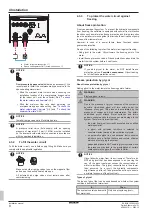
▪ In
Weather dependent
LWT setpoint mode, the scheduled
actions consist of desired shift actions, either preset or custom.
#
Code
Description
[2.1]
N/A
▪ 0:
No
▪ 1:
Yes
5.2.6
Configuration wizard: Additional zone
The most important settings for the additional leaving water zone
can be set here.
Emitter type
For more info about this functionality, see
#
Code
Description
[3.7]
[2‑0D]
▪ 0:
Underfloor heating
▪ 1:
Fancoil unit
▪ 2:
Radiator
Control
The control type is displayed here, but cannot be adjusted. It is
determined by the control type of the main zone. For more info about
the functionality, see
"Configuration wizard: Main zone"
#
Code
Description
[3.9]
N/A
▪ 0:
Leaving water
if the control type
of the main zone is
Leaving water
.
▪ 1:
External room thermostat
if the
control type of the main zone is
External room thermostat
or
Room
thermostat
.
Setpoint mode
For more info about this functionality, see
#
Code
Description
[3.4]
N/A
▪ 0:
Fixed
▪ 1:
WD heating, fixed cooling
▪ 2:
Weather dependent
If you choose
WD heating, fixed cooling
or
Weather
dependent
, the next screen will be the detailed screen with weather-
dependent curves. Also see
"Detailed screen with weather-
Schedule
Indicates if the desired leaving water temperature is according to a
schedule. Also see
"Configuration wizard: Main zone"
17].
#
Code
Description
[3.1]
N/A
▪ 0:
No
▪ 1:
Yes
5.2.7
Detailed screen with weather-dependent
curve
When weather-dependent (WD) operation is active the desired
leaving water or tank temperature is determined automatically
depending on the averaged outdoor temperature. When the outdoor
temperature is lower the leaving water or tank temperature will need
to be higher as the water pipes will be colder and vice versa.
Slope and offset
Define the weather-dependent curve by its slope and offset:
▪ Change the
slope
to differently increase or decrease the
temperature of the leaving water for different ambient
temperatures. For example, if leaving water temperature is in
general fine but at low ambient temperatures too cold, raise the
slope so that leaving water temperature is heated increasingly
more at decreasingly lower ambient temperatures.
▪ Change the
offset
to equally increase or decrease the
temperature of the leaving water for different ambient
temperatures. For example, if leaving water temperature is always
a bit too cold at different ambient temperatures, shift the offset up
to equally increase the leaving water temperature for all ambient
temperatures.
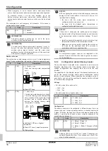
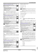
Examples
Weather-dependent curve when slope is selected:
X1
X2
c
d
e
Y1
Y2
Y3
Y4
a
b
Weather-dependent curve when offset is selected:
Y1
Y2
Y3
Y4
X1
X2
a
b
c
d
e
Possible actions on this screen
Select slope or offset.
Increase or decrease the slope/offset.
When slope is selected: set slope and go to offset.
When offset is selected: set offset.
Confirm changes and return to the submenu.
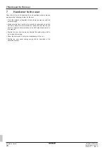
2-points WD curve
The weather-dependent curve is defined by two setpoints:
▪ Setpoint (X1, Y2)
▪ Setpoint (X2, Y1)
Weather-dependent curve:
Y1
Y2
X1
X2
a


