


5 Configuration
Installation manual
14
EABH/9W
Daikin Altherma 3 H W
4P644479-1 – 2020.12
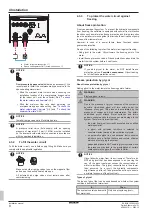
NOTICE
When closing the indoor unit cover, make sure that the
tightening torque does NOT exceed 4.1 N•m.
5
Configuration
INFORMATION
Cooling is only applicable in case of:
▪ Reversible models
▪ Heating only conversion kit (EKHBCONV)
5.1
Overview: Configuration
This chapter describes what you have to do and know to configure
the system after it is installed.
NOTICE
This chapter explains only the basic configuration. For
more detailed explanation and background information,
see the installer reference guide.
Why
If you do NOT configure the system correctly, it might NOT work as
expected. The configuration influences the following:
▪ The calculations of the software
▪ What you can see on and do with the user interface
How
You can configure the system via the user interface.
▪
First time – Configuration wizard.
When you turn ON the user
interface for the first time (via the unit), the configuration wizard
starts to help you configure the system.
▪
Restart the configuration wizard.
If the system is already
configured, you can restart the configuration wizard. To restart the
configuration
wizard,
go
to
Installer
settings
>
Configuration wizard
. To access
Installer settings
, see
"To access the most used commands"
▪
Afterwards.
If necessary, you can make changes to the
configuration in the menu structure or the overview settings.
INFORMATION
When the configuration wizard is finished, the user
interface will show an overview screen and request to
confirm. When confirmed, the system will restart and the
home screen will be displayed.
Accessing settings – Legend for tables
You can access the installer settings using two different methods.
However, NOT all settings are accessible via both methods. If so,
the corresponding table columns in this chapter are set to N/A (not
applicable).
Method
Column in tables
Accessing settings via the breadcrumb in the
home menu screen
or the
menu structure
.
To enable breadcrumbs, press the button
in the home screen.
#
For example: [2.9]
Accessing settings via the code in the
overview field settings
.
Code
For example: [C-07]
See also:
▪
"To access the installer settings"
▪
"5.4 Menu structure: Overview installer settings"
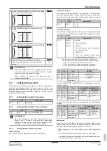
5.1.1
To access the most used commands
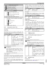
To change the user permission level
You can change the user permission level as follows:
1
Go to [B]:
User profile
.
User profile
B
2
Enter the applicable pin code for the user permission
level.
—
▪ Browse through the list of digits and change the
selected digit.
▪ Move the cursor from left to right.
▪ Confirm the pin code and proceed.
Installer pin code
The
Installer
pin code is
5678
. Additional menu items and
installer settings are now available.
5678
Installer
Advanced user pin code
The
Advanced user
pin code is
1234
. Additional menu items for the
user are now visible.
1234
Advanced user
User pin code
The
User
pin code is
0000
.
0000
User
To access the installer settings
1
Set the user permission level to
Installer
.
2
Go to [9]:
Installer settings
.
To modify an overview setting
Example:
Modify [1‑01] from 15 to 20.
Most settings can be configured via the menu structure. If for any
reason it is required to change a setting using the overview settings,
then the overview settings can be accessed as follows:
1
Set the user permission level to
Installer
change the user permission level"
—
2
Go to [9.I]:
Installer settings
>
Overview
field settings
.


