Daikin Altherma 3 H W Installation Manual Download Page 11

4 Installation

Installation manual

11

EABH/9W
Daikin Altherma 3 H W
4P644479-1 – 2020.12
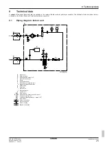
4.4.4

To connect the backup heater power
supply

CAUTION

If the indoor unit has a tank with a built‑in electrical booster
heater, use a dedicated power circuit for the backup heater
and booster heater. NEVER use a power circuit shared by
another  appliance.  This  power  circuit  must  be  protected
with the required safety devices according to the applicable
legislation.

CAUTION

To  guarantee  the  unit  is  completely  earthed,  always
connect  the  backup  heater  power  supply  and  the  earth
cable.

The backup heater capacity can vary, depending on the indoor unit
model.  Make  sure  that  the  power  supply  is  in  accordance  with  the
backup heater capacity, as listed in the table below.

Backup

heater type

Backup

heater

capacity

Power

supply

Maximum

running

current

Z

max

*6V

2 kW

1N~ 230 V

(a)

9 A

4 kW

1N~ 230 V

(a)

17 A

(b)(c)

0.22 Ω

6 kW

1N~ 230 V

(a)

26 A

(b)(c)

0.22 Ω

2 kW

3~ 230 V

(d)

5 A

4 kW

3~ 230 V

(d)

10 A

6 kW

3~ 230 V

(d)

15 A

*9W

3 kW

3N~ 400 V

4 A

6 kW

3N~ 400 V

9 A

9 kW

3N~ 400 V

13 A

(a)

6V

(b)

Electrical equipment complying with EN/IEC 61000-3-12
(European/International Technical Standard setting the limits for
harmonic currents produced by equipment connected to public
low-voltage systems with input current >16 A and ≤75 A per
phase).

(c)

This equipment complies with EN/IEC 61000‑3‑11 (European/
International Technical Standard setting the limits for voltage
changes, voltage fluctuations and flicker in public low-voltage
supply systems for equipment with rated current ≤75 A) provided
that the system impedance Z

sys

 is less than or equal to Z

max

 at the

interface point between the user's supply and the public system. It
is the responsibility of the installer or user of the equipment to
ensure, by consultation with the distribution network operator if
necessary, that the equipment is connected only to a supply with
a system impedance Z

sys

 less than or equal to Z

max

.

(d)

6T1

Connect the backup heater power supply as follows:

a

b

X6M

F1B

Q1DI

a

Factory-mounted cable connected to the contactor of the
backup heater, inside the switch box (K5M)

b

Field wiring (see table below)

Model (power

supply)

Connections to backup heater power

supply

*6V (6V: 1N~ 230 V)

1N~, 50 Hz

230 V AC

SWB

4
3

6
5

2
1

K5M

14
13

Q1DI

1

2

3

4

5

6

7

8

F1B

I

I

I

I

N

L

X6M

BRN

GRY

BLU1

BLU2

*6V (6T1: 3~ 230 V)

SWB

3~, 50 Hz

230 V AC

4
3

6
5

2
1

K5M

14
13

1

2

3

4

5

6

7

8

F1B

I

I

I

I

Q1DI

L1 L2 L3

X6M

BRN

GRY

BLU1

BLU2

*9W (3N~ 400 V)

3N~, 50 Hz

400 V AC

SWB

Q1DI

L1 L2 L3 N

1

2

3

4

5

6

7

8

F1B

I

I

I

I

X6M

2
1

K5M

4
3

6
5

14
13

BRN

GRY

BLK

BLU

F1B  Overcurrent fuse (field supply). Recommended fuse:

4‑pole; 20 A; curve 400 V; tripping class C.

K5M Safety contactor (in the switch box)

Q1DI Earth leakage circuit breaker (field supply)

SWB Switch box

X6M Terminal (field supply)

Summary of Contents for Altherma 3 H W

Page 1: ...Installation manual Daikin Altherma 3 H W English Installation manual Daikin Altherma 3 H W EABH16DF6V EABH16DF9W EABX16DF6V EABX16DF9W...

Page 2: ...y odpov daj n sleduj c m norm m nebo normativn m dokument m u skladu sa slijede im standardom ima ili drugim normativnim dokumentom ima uz uvjet da se oni koriste u skladu s na im uputama 16 17 18 19...

Page 3: ...pendent curve 18 5 2 8 Configuration wizard Tank 19 5 3 Settings menu 19 5 3 1 Main zone 19 5 3 2 Additional zone 19 5 3 3 Information 20 5 4 Menu structure Overview installer settings 21 6 Commission...

Page 4: ...5 35 C Domestic hot water production 5 35 C INFORMATION Cooling is only applicable in case of Reversible models Heating only models conversion kit EKHBCONV Mind the measurement guidelines Maximum hei...

Page 5: ...above the heat exchanger coil The booster heater must be located above the heat exchanger coil NOTICE Performance Performance data for third party tanks CANNOT be provided and performance CANNOT be g...

Page 6: ...Overview 1 2 3 1 4 4 1 Front panel 2 Switch box cover 3 Switch box 4 User interface panel Open 1 Remove the front panel 2 2 1 3 2 If you have to connect electrical wiring remove the switch box cover...

Page 7: ...he drain hose to the drain Water coming from the pressure relief valve is collected in the drain pan You must connect the drain pan to an appropriate drain according to the applicable legislation 1 Co...

Page 8: ...circuit against freezing Add glycol to the water Glycol lowers the freezing point of the water Install freeze protection valves Freeze protection valves drain the water from the system before it can...

Page 9: ...se freeze protection valves to drain the water from the system before it can freeze Install freeze protection valves field supply at all lowest points of the field piping Normally closed valves locate...

Page 10: ...y factory mounted cable Power supply for backup heater CAUTION Do NOT push or place redundant cable length in the unit 4 4 3 To connect the main power supply 1 Connect the main power supply In case of...

Page 11: ...er phase c This equipment complies with EN IEC 61000 3 11 European International Technical Standard setting the limits for voltage changes voltage fluctuations and flicker in public low voltage supply...

Page 12: ...ck the polarity The positive polarity MUST be connected to X5M 6 and X5M 4 the negative polarity to X5M 5 and X5M 3 1 Connect the electricity meters cable to the appropriate terminals as shown in the...

Page 13: ...tat normally closed cable to the appropriate terminals as shown in the illustration below X5M 9 10 2 Fix the cable with cable ties to the cable tie mountings NOTICE Make sure to select and install the...

Page 14: ...be displayed Accessing settings Legend for tables You can access the installer settings using two different methods However NOT all settings are accessible via both methods If so the corresponding ta...

Page 15: ...st be set on the user interface For units with a built in backup heater the type of heater can be viewed but not changed Code Description 9 3 1 E 03 3 6V 4 9W Domestic hot water The following setting...

Page 16: ...nd the zone with the highest water temperature is configured as the additional zone NOTICE If there are 2 zones and the emitter types are wrongly configured water of high temperature can be sent towar...

Page 17: ...T in heating 0 Underfloor heating Maximum 55 C Variable 1 Fancoil unit Maximum 55 C Variable 2 Radiator Maximum 65 C Fixed 8 C NOTICE Average emitter temperature Leaving water temperature Delta T 2 T...

Page 18: ...n 3 1 N A 0 No 1 Yes 5 2 7 Detailed screen with weather dependent curve When weather dependent WD operation is active the desired leaving water or tank temperature is determined automatically dependin...

Page 19: ...t up until the storage comfort temperature has been reached It is the higher desired temperature when a storage comfort action is scheduled Additionally a storage stop can be programmed This feature p...

Page 20: ...44479 1 2020 12 Code Description 3 A C 06 External room thermostat type for the additional zone 1 1 contact 2 2 contacts 5 3 3 Information Dealer information The installer can fill in his contact numb...

Page 21: ...librium temperature Operation 9 4 Booster heater Capacity BSH allowance schedule BSH eco timer Operation 9 6 Balancing Space heating priority Priority temperature Offset BSH setpoint Minimum running t...

Page 22: ...tightened The fuses or locally installed protection devices are installed according to this document and have NOT been bypassed The power supply voltage matches the voltage on the identification labe...

Page 23: ...evel 414 2 Go to A 2 Commissioning Actuator test run 3 Select a test from the list Example Pump 4 Select OK to confirm Result The actuator test run starts It stops automatically when ready 30 min To s...

Page 24: ...in the operation manual with the actual settings Make sure that the user has the printed documentation and ask him her to keep it for future reference Inform the user that he can find the complete doc...

Page 25: ...diagram Indoor unit 3D120613A R2T R1T B1PW B1L A B B e e k k f i g c a b h j d h S1L i A Indoor unit B Field installed a Space heating water OUT b Water IN connection c Pump d Expansion vessel e Shut...

Page 26: ...t pump convector Safety thermostat Safety thermostat Add LWT Additional leaving water temperature On OFF thermostat wired On OFF thermostat wired On OFF thermostat wireless On OFF thermostat wireless...

Page 27: ...ater pump output DHW pump Domestic hot water pump Electrical meters Electricity meters For safety thermostat For safety thermostat Inrush Inrush current Max load Maximum load English Translation Norma...

Page 28: ...thermostat Heat pump convector main and or additional zone 5 core for C H operation 4 core for H only operation 3 core for C H operation 2 core for H only operation 2 core 2 core communication 2x0 75...

Page 29: ......

Page 30: ......

Page 31: ......

Page 32: ...4P644479 1 2020 12 Copyright 2018 Daikin 4P644479 1 0000000W Verantwortung f r Energie und Umwelt...

Reviews: