Daikin AGZ030EH Installation, Operation And Maintanance Manual Download Page 63

IOM 1206-1

63

Component Operation

Alert/Lockout Codes (Flashing Red LED)

Code 1 – Motor High Temperature: The module will flash the 
red 

Alert 

LED one time indicating the motor is onerheating . 

A code 1 

Alert 

will open the M2-M1 contacts. The 

Alert 

will 

reset after 30 minutes. Five consecutive Code 1 

Alerts 

will 

lockout the compressor. Once the module has locked out the 
compressor, a power cycle or Modbus reset command will be 
required for the lockout to be cleared.

Code 2 – Open/Shorted Motor Thermistor: The module will 
flash the red 

Alert 

LED two times indicating the motor PTC 

thermistor circuit has an open/shorted thermistor chain (see 

Table 2

). A Code 2 

Alert 

will open the M2-M1 contacts. The 

Alert 

will reset after 30 minutes and the M2-M1 contacts will 

close if the resistance of the motor PTC circuit is back in the 
normal range. The module will lockout the compressor and a 
power cycle or Modbus reset command will be required to 
clear the lockout.

Code 3 – Short Cycling: The module will flash the red 

Alert 

LED three times indicating the compressor is locked out due to 
short cycling. Once locked out the compressor, a power cycle 
or Modbus reset command will be required to clear the 
lockout.

Code 4 – Scroll High Temperature: The module will flash the 
red 

Alert 

LED four times indicating the over-temperature 

condition. A Code 4 

Alert 

will open the M2-M1 contacts.The 

Alert 

will reset after 30 minutes. Once the module has locked 

out the compressor, a power cycle or Modbus reset command 
will be required to clear the lockout.

Code 5 – Reserved for Future Use

Code 6 – Missing Phase: The module will flash the red 

Alert 

LED six times indicating a missing phase. The 

Alert 

will reset 

after 5 minutes and the module will lockout the compressor 
after 10 consecutive Code 6 

Alerts

. Once locked out, a power 

cycle or Modbus reset is required.

Code 7 – Reverse Phase: The module will flash the red 

Alert 

LED seven times indicating a reverse phase in two of the three 
compressor leads.  The modules will lockout the compressor 
after one Code 7 

Alert

. A power cycle or Modbus reset 

command will be required to clear the lockout.

Code 8 – Reserved For Future Use

Code 9 – Module Low Voltage: The module will flash the red 

Alert 

LED nine times indicating low module voltage for more 

than 5 seconds. The 

Alert 

will reset after 5 minutes and the 

M2-M1 contacts will close if the T2-T1 voltage is above the 
reset value.

Note: 

If a compressor with CoreSense Communications fails in 

the field, the CoreSense module should remain with the 

failed compressor so the manufacturer’s technicians can 

download the CoreSense data to assist with determining 

the root cause of compressor failure.
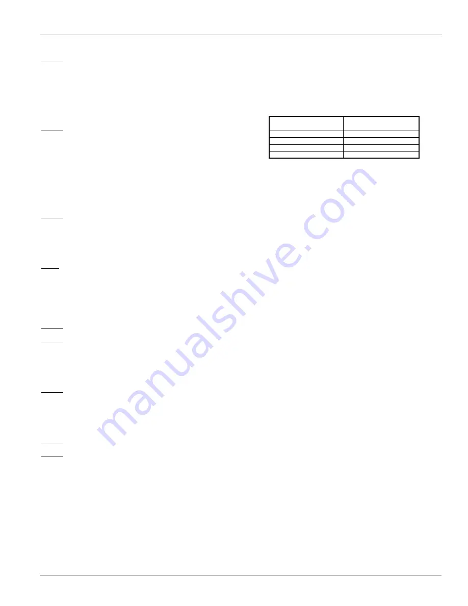
Filter-Driers

For units with optional replaceable core filter driers, each 
refrigerant circuit is furnished with a replaceable core type 
filter-drier. The core assembly of the replaceable core drier 
consists of a filter core held tightly in the shell in a manner that 
allows full flow without bypass. Pressure drop across the filter 
drier must not exceed the following values. 

A condenser liquid line service valve is provided for isolating 
the charge in the condenser, but also serves as the point from 
which the liquid line can be pumped out. With the line free of 
refrigerant, the filter-drier core(s) can be easily replaced.

System Adjustment

To maintain peak performance at full load operation, the 
system superheat and liquid subcooling may require 
adjustment. Read the following subsections closely to 
determine if adjustment is required.

Liquid Line Sight Glass 

The color of the moisture indicator is an indication of the 
dryness of the system and is extremely important when the 
system has been serviced. Immediately after the system has 
been opened for service, the element may indicate a wet 
condition. It is recommended that the equipment operate for 
approximately 12 hours to allow the system to reach 
equilibrium before deciding if the system requires a change of 
drier cores.

Bubbles in the sight glass at constant full load indicates a 
shortage of refrigerant, a plugged filter-drier, or a restriction in 
the liquid line. However, it is not unusual to see bubbles in the 
sight glass during changing load conditions.

Refrigerant Charging

Liquid line subcooling at the liquid shut-off valve should be 
between 15 and 20 degrees F at full load.  If the unit is at 
steady full load operation and bubbles are visible in the sight 
glass, then check liquid subcooling.

Expansion Valve

The expansion valve's function is to keep the evaporator 
supplied with the proper amount of refrigerant to satisfy the 
load conditions.

Before adjusting superheat, check that unit charge is correct 
and liquid line sight glass is full with no bubbles and that the 
circuit is operating under stable, full load conditions.

The suction superheat for the suction leaving the evaporator is 
set at the factory for 10 to 12 degrees F at full load. To have 

PERCENT CIRCUIT

LOADING (%)

DROP ACROSS 

PSI (KPA)

100%

10 (69)

75%

8 (55.2)

50%

5 (34.5)

25%

4 (27.6)

Summary of Contents for AGZ030EH

Page 1: ...tion Operation and Maintenance Manual IOM 1206 1 Air Cooled Scroll Compressor Chiller Group Chillers Part Number IOM1206 1 Date May 2014 2014 Daikin Applied AGZ030EH AGZ070EH Packaged Chillers R 410A...

Page 2: ...ll 73 Hazard Identification 2014 Daikin Applied Illustrations and data cover the Daikin Applied product at the time of publication and we reserve the right to make changes in design and construction a...

Page 3: ...nit leaves the factory Handling Be careful to avoid rough handling of the unit Do not push or pull the unit from anything other than the base Block the pushing vehicle away from the unit to prevent da...

Page 4: ...s to allow the required unit air flow to reach the coils Failure to do so will result in a capacity reduction and an increase in power consumption No obstructions are allowed above the unit at any hei...

Page 5: ...requirements are met and service access is provided Pit covers must have abundant open area at least equal to the chiller footprint A solid wall surrounding a unit is substantially a pit and this dat...

Page 6: ...construction Install pressure gauges in the inlet and outlet water lines to the evaporator Measure pressure drop through the evaporator and compare to flow as shown on page 18 Vibration eliminators a...

Page 7: ...re required to isolate the unit from the piping during unit servicing 3 Manual or automatic air vent valves at the high points of the system Drains must be installed at the lowest points in the system...

Page 8: ...m to provide freeze protection Freeze point should be approximately ten degrees F below minimum design ambient temperature 3 The addition of thermostatically controlled heat and insulation to exposed...

Page 9: ...ed for outdoor installation They can freeze and not indicate a no flow conditions Glycol Solutions The use of a glycol water mixture in the evaporator to prevent freezing will reduce system capacity a...

Page 10: ...67 484 881 400 548 249 453 205 1022 464 844 383 601 273 496 225 A GZ 045E 3094 1403 3112 1412 1051 477 832 377 676 307 535 243 1021 463 809 367 715 324 567 257 A GZ 050E 3093 1403 3114 1412 1049 476 8...

Page 11: ...77 398 733 332 588 267 1065 483 854 387 772 350 619 281 A GZ 050E 3317 1505 3338 1514 1098 498 886 402 737 334 595 270 1071 486 864 392 776 352 627 284 A GZ 055E 3334 1512 3356 1522 1102 500 891 404 7...

Page 12: ...RECESSED GR IP RIBS 500 13NC 2B R4 R 4 VM C V M C RP 4 Rubber in Shear RIS CP 2 Spring Isolator Spring Isolator Kit Numbers Aluminum Fins Copper Fins 030 332320102 332320132 035 332320102 332320132 04...

Page 13: ...Brown Brown Brown Dk Grn Dk Prpl Dk Prpl Black 030 AGZ E Model Rubber In Shear RIS Mounts Spring Isolator Mountings 035 040 045 050 055 060 065 070 M1 M2 M3 M4 M5 M6 M7 M8 M1 M2 M3 M4 M5 M6 M7 M8 RP...

Page 14: ...HOLE FOR ATTACHMENT TO CONCRETE 6 TYP 3 4 REMOVABLE ADJUSTING BOLT LIMIT STOPS NOT SHOWN IN TOP VIEW FOR CLARITY 2 7 8 2 1 4 7 6 1 4 1 1 8 8 5 1 8 10 1 4 8 3 8 1 2 5 3 4 1 4 3 8 ELASTOMERIC SNUBBER 3...

Page 15: ...85 2410 85 2410 85 2410 85 2410 85 2410 Staging 4 Stages If Circuit is in Lead 0 25 50 75 100 0 25 50 75 100 0 23 50 73 100 0 27 50 77 100 0 25 50 75 100 0 25 50 75 100 MICROCHANNEL CONDENSER Coil In...

Page 16: ...119 110 3119 110 3119 110 3119 Staging 4 Stages If Circuit is in Lead 0 25 50 75 100 0 25 50 75 100 0 25 50 75 100 0 25 50 75 100 0 23 50 73 100 0 27 50 77 100 MICROCHANNEL CONDENSER Coil Inlet Face A...

Page 17: ...3119 110 3119 152 4309 110 3119 152 4309 Staging 4 Stages If Circuit is in Lead 0 25 50 75 100 0 25 50 75 100 0 25 50 75 100 0 25 50 75 100 0 21 50 71 100 0 28 50 78 100 MICROCHANNEL CONDENSER Coil In...

Page 18: ...5 8 42 5 154 4 37 7 9 7 112 6 D 45E 40 9 2 3 2 6 6 8 63 9 5 3 4 0 15 8 102 2 13 2 6 5 39 4 170 4 34 4 10 8 102 7 E 50E 46 4 2 7 2 9 7 9 72 5 6 2 4 6 18 5 115 9 15 2 7 3 45 3 193 2 40 0 12 2 119 6 F 55...

Page 19: ...Limitations 1 Within 10 percent of nameplate rating 2 Voltage unbalance not to exceed 2 with a resultant current unbalance of 6 to 10 times the voltage unbalance per NEMA MG 1 2009 Standard Rev 1 201...

Page 20: ...2 70 TB2 69 TB2 68 TB2 61 TB2 TB1 22 TB1 1A TO COMPRESSOR S AND FAN MOTORS ALARM BELL RELAY 120 VAC FU5 T1 FU6 CONTROL CIRCUIT FUSE SEE NOTE 1 FU4 REMOTE STOP SWITCH BY OTHERS TB2 TB2 43 83 ALARM BELL...

Page 21: ...TB2 68 TB2 61 TB2 TB1 22 TB1 1A TO COMPRESSOR S AND FAN MOTORS ALARM BELL RELAY 120 VAC FU5 T1 FU6 CONTROL CIRCUIT FUSE SEE NOTE 1 FU4 REMOTE STOP SWITCH BY OTHERS TB2 TB2 43 83 ALARM BELL OPTION N N...

Page 22: ...0V 60 90 100 100 1 14 2 0 1 12 1 0 575V 60 75 90 90 1 14 2 0 1 12 1 0 400V 50 94 110 110 1 14 2 0 1 4 300MCM 208V 60 241 250 250 1 2 600MCM 2 3 0 500MCM 230V 60 241 250 250 1 2 600MCM 2 3 0 500MCM 380...

Page 23: ...1 0 49 60 60 1 14 2 0 1 12 1 0 208V 60 127 150 175 1 14 2 0 1 6 350MCM 127 150 175 1 14 2 0 1 6 350MCM 230V 60 127 150 175 1 14 2 0 1 6 350MCM 127 150 175 1 14 2 0 1 6 350MCM 380V 60 69 90 90 1 14 2 0...

Page 24: ...ler also provides the operator with a warning of limit pre alarm conditions Controller Inputs and Outputs Main Controller Table 21 Analog Inputs Table 22 Analog Outputs Table 23 Digital Inputs Table 2...

Page 25: ...cuit 1 or Unit PVM GFP Fault No fault Description Output Off Output On DO1 Compressor 1 Compressor Off Compressor On DO2 Compressor 3 Compressor Off Compressor On DO3 Compressor 5 Compressor Off Compr...

Page 26: ...34146 Pressure Pressure inputs will be read using 0 to 5 volt ratiometric sensors Nominal voltage range will be 0 5 to 4 5 volts Pressure on the low side will be measured using Daikin part number 3317...

Page 27: ...ion Power Input Single Point Single Point Multi Point Evap Control 1 Only 1 Only 2 Only Auto 1 Primary 2 Primary Number of Compressors 4 4 6 Expansion Valve Type Thermal Thermal Electronic Fan VFD ena...

Page 28: ...F 32 22 to 48 9 C 90 to 120 F Condenser Target 67 32 2 C 90 F 32 22 to 48 9 C 90 to 120 F Condenser Target 50 32 2 C 90 F 29 44 to 43 3 C 85 to 110 F Condenser Target 33 29 4 C 85 F 29 44 to 43 3 C 85...

Page 29: ...ice personnel Operator password 2526 Entering Passwords Passwords are entered on the first screen on the unit controller If the wrong password is entered a message will temporarily appear stating this...

Page 30: ...in terms of delta T also The term Effective Full Capacity Delta T means the approximate temperature delta that would be observed with the unit running at full capacity for the given flow Nominal flow...

Page 31: ...itches between cool mode and ice mode if they are available and the control source is set to local The BAS mode request switches between cool mode and ice mode if they are both available and the contr...

Page 32: ...to 150 seconds Therefore after the control is powered up no compressor can start for 150 seconds In addition the motor protect inputs are ignored during this time so as to avoid tripping a false alarm...

Page 33: ...to Motor Prot Delay Unit State Auto and MP start up delay is active 3 Off Ice Mode Timer Unit State Off Unit Mode Ice and Ice Delay Active 4 Off OAT Lockout Unit State Off and Low OAT Lockout is activ...

Page 34: ...ic above is still used When the evaporator is not in the run state the run hours of the pumps will be compared The pump with the least hours will be designated as the primary at this time LWT Target T...

Page 35: ...ally start first and compressors with more run hours will normally stop first If possible circuits will be balanced in stage If a circuit is unavailable for any reason the other circuit shall be allow...

Page 36: ...tore Option RapidRestore is an option that can be added to AGZ chillers The general purpose of the option is to allow the capability to restart more quickly and to load faster than normal Enabling The...

Page 37: ...faster time to full capacity while maintaining stable operation within each circuit Assuming both circuits are able to run the effective unit stage up delay will be 30 to 35 seconds so it will load a...

Page 38: ...38 IOM 1206 1 Unit Controller Operation Figure 16 Four Compressor Units Power Lost and Restored...

Page 39: ...IOM 1206 1 39 Unit Controller Operation Figure 17 Four Compressor Units Backup Chiller Constant Power...

Page 40: ...it Control Logic Circuit Enabling A circuit should be enabled to start if the following conditions are true Circuit switch is closed No circuit alarms are active Circuit Mode set point is set to Enabl...

Page 41: ...OAT start is initiated if the condenser refrigerant saturated temperature is less than 29 5 C 85 1 F when the first compressor starts Once the compressor starts the circuit is in a low OAT start stat...

Page 42: ...es below show the outputs energized for each stage Condenser Target A condenser target should be selected from the setpoints based on the number of compressors on the unit and the number of compressor...

Page 43: ...tage is 0 When the fan stage is greater than 0 the VFD speed signal should be enabled and control the speed as needed Stage Up Compensation In order to create a smoother transition when another fan is...

Page 44: ...alve maximum position may be increased if after two minutes both the suction superheat is greater than 7 2 C 13 F and the expansion valve has been within 5 of its current maximum position The maximum...

Page 45: ...a the keypad or via the BAS clear alarm command If active via trigger condition 1 When the alarm occurs due to this trigger it can auto reset the first two times each day with the third occurrence bei...

Page 46: ...and the extension module is working for 5 seconds or Expansion Valve Type Thermal Unit Problem Alarms Evaporator Pump 1 Failure Trigger Unit is configured with primary and backup pumps pump 1 is runn...

Page 47: ...ure goes below the Low Evaporator Pressure Unload set point a timer starts If this timer exceeds the freeze time then a freezestat trip occurs If the evaporator pressure rises to the unload set point...

Page 48: ...r the current day and the count of occurrences for each of the previous 7 days Unit Events Unit Power Restore Trigger Unit controller is powered up Action Taken None Reset None Circuit Events Low Evap...

Page 49: ...stores the last 50 occurrences or resets that occur When an alarm or event occurs it is put into the first slot in the alarm log and all others are moved down one dropping the last entry The date and...

Page 50: ...here are lines above and below the currently displayed line The selected line is highlighted Each line on a screen can contain status only information or include changeable data fields setpoints When...

Page 51: ...iously displayed page If the Back button is repeatedly pressed the display continues to revert one page back along the current navigation path until the main menu is reached When the Menu Home Button...

Page 52: ...s temperatures values and setpoints The first line is Evap LWT rotate wheel until Cool LWT 1 is highlighted Press the wheel to enter edit mode Rotate wheel until new setpoint is reached then press whe...

Page 53: ...ber R Alarm Entry 25 R Unit Serial Number R Starter Model Number s Starter Serial Number s BSP Version R Starter Model Numbers Application Version R Circuit 1 R W HMI GUID R Circuit 2 R W OBH GUID R C...

Page 54: ...to the Motor The AC motor must be connected only to the inverter s output terminals The output terminals are uniquely labeled to differentiate them from the input terminals with the designations U T1...

Page 55: ...ng this button will return to the Frequency Reference display 3 Moves the cursor to the right Resets the drive to clear a fault situation 4 RUN Key Starts the drive in LOCAL mode 5 Up Arrow Key Scroll...

Page 56: ...e is assigned to the MEMOBUS Modbus CommunicationInputs of the drive OP Displayed when the frequency reference is assigned to an Option Unit of the drive RP Displayed when the frequency reference is a...

Page 57: ...r than the operator is selected for Run command and frequency reference control REMOTE During run During deceleration to stop When a Run command is input and frequency reference is 0 Hz While the driv...

Page 58: ...cator LED flashes Remove the cause of the problem to reset a minor fault or alarm Operation Errors An operation error occurs when parameter settings conflict or do not match hardware settings such as...

Page 59: ...h III chiller BACnet and LONWORKS ED 15121 Protocol Information for MicroTech III chiller Modbus WARNING Electrical Shock Hazard Before servicing or inspecting the equipment disconnect power to the un...

Page 60: ...the Emergency Stop position 4 Put both circuit 1 2 switches to the Pumpdown and Stop position 5 Apply power to the unit The panel Alarm Light will stay on until S1 is closed Ignore the Alarm Light fo...

Page 61: ...both refrigerant circuit discharge valves if applicable 5 If chilled water system is not drained maintain power to the evaporator heater to prevent freezing Maintain heat tracing on the chilled water...

Page 62: ...mum of 10oF 23 3oC The control looks at the saturated discharge temperature and varies pressure at the target temperature This temperature is established as an input to a setpoint screen labeled Sat C...

Page 63: ...value Note If a compressor with CoreSense Communications fails in the field the CoreSense module should remain with the failed compressor so the manufacturer s technicians can download the CoreSense...

Page 64: ...s AGZ 030E through 070E the evaporator is a compact high efficiency dual circuit brazed plate to plate type heat exchanger consisting of parallel stainless steel plates The evaporator is protected wit...

Page 65: ...the condensing process refrigerant in the coil passes through the micro channel flat tubes resulting in higher efficiency heat transfer from the refrigerant to the airstream In the unlikely occurence...

Page 66: ...ing is essential to extend the life of an ElectroFin Coated Coil and is required to maintain warranty coverage Coil cleaning shall be part of the unit s regularly scheduled maintenance procedures Fail...

Page 67: ...hood two inlet screens with filters necessary controls and wiring to allow operation to 125 F 52 C The option can be factory or field installed as a kit It must be supplied on units operating at ambi...

Page 68: ...review Note 3 X Visually inspect unit for loose or damaged components X Inspect thermal insulation for integrity X Clean and paint as required X Electrical Check terminals for tightness tighten as nec...

Page 69: ...r pressurize systems with oxygen or ref air mix R 410A R 407C R 134A R 22 are flammable with low air mix Wear protective clothing Impervious gloves and splash goggles should be worn Avoid contact with...

Page 70: ...charge to the recommended liquid line sub cooling approximately 14 20 degrees F typical Verify the suction superheat 10 degrees F for EEVs and 10 12 degrees F for TXVs at full load conditions Use sta...

Page 71: ...require replacement of the solenoid coil or of the entire valve assembly The solenoid coil can be checked to see that the stem is magnetized when energized by touching a screwdriver to the top of the...

Page 72: ...irculation 6 Clean coil 7 Correct Low Discharge Pressure 1 Refrigerant flood back 1 Correct 2 Wind blowing into coil at low ambient 2 Shield coil from direct wind Wind guards are available 3 Faulty co...

Page 73: ...superheat 3 Crankcase heater burnout 3 Replace crankcase heater Motor Overload Relays or Circuit Breakers Open 1 Low voltage during high load conditions 1 Check supply voltage for excessive line drop...

Page 74: ...UP PROCEDURE II Pre Start Up Checklist Pre Start Up Checklist All NO checks require an explanation under Description Please check yes or no YES NO A Is the unit free of visible shipping damage corrosi...

Page 75: ...Air Temperature ________ F C F C M Are all service and liquid line valves open N Have all shipping hold down plates been removed O Has a flow switch been installed per the IM bulletin P Has the chill...

Page 76: ...quid Line Temperature F C F C Subcooling F C F C G Circuit 2 Refrigerant Temperatures Saturated Evaporator Temperature F C F C Suction Line Temperature F C F C Suction Superheat F C F C Saturated Cond...

Page 77: ...g kPa psig kPa Q High Pressure Cut Out psig kPa psig kPa R Unit Type S Number of Compressors T Number of Stages U Number of Fan Stages V Software Version VII FOR HEAT RECOVERY CHILLERS ONLY Must Be Ta...

Page 78: ...Applied equipment is sold pursuant to its standard terms and conditions of sale including Limited Product Warranty Consult your local Daikin Applied representative for warranty details To find your l...

Reviews: