


4
Set-up and installation
Installation and operating instructions
16
Daikin/ROTEX A2 F
Oil condensing boiler A2 F
008.1546499_01 – 03/2018 – EN
4.4.2
Installing the device
Precondition
▪ The installation site complies with applicable country-specific reg-
ulations and meets the minimum requirements described in
.
Installation
1
Remove the packaging completely (edge protection as well) and
dispose of it in an environment-friendly manner.
2
Installing the A2 F at the installation site. Only lift or move the
device by the recessed grips provided for this purpose.
3
Position the A2 F in such a way that the connection points of the
oil hoses or mounting position of the oil filter, the ducting of the
heating pipes and the flue gas pipe can be operated without re-
strictions.
4
Check the horizontal position and correct installation height of
the A2 F. Slight unevennesses can be compensated by four
height-adjustable feet.
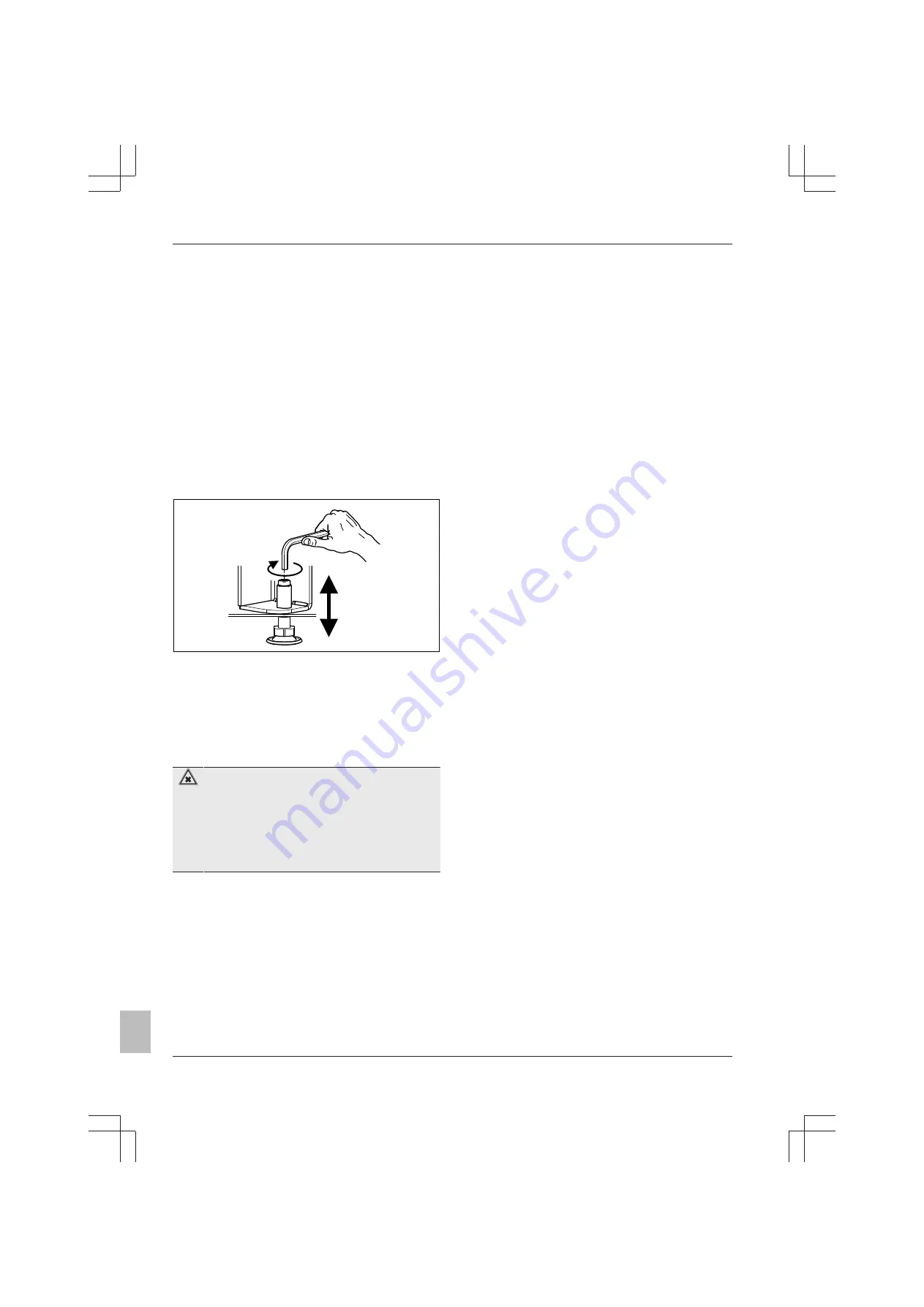
Height adjustment
Image 4-5 Height-adjustable feet
▪ Adjust the height of the A2 F using the screw with an Allen key
SW 5 mm or a 17 mm open-ended spanner.
4.5
Air/flue gas system (LAS)
4.5.1
General instructions for the flue gas
system
DANGER: RISK OF POISONING
There will be a
risk of poisoning
caused by flue gas es-
caping within enclosed rooms that are inadequately ventil-
ated.
▪ Install only approved flue gas systems.
▪ Depending on the installation variant, the stipulated
ventilation and rear ventilation must be ensured (see
).
Minimum requirements
For the design and measurement of the flue gas system, the re-
spectively valid national fire code ordinance or the country-specific
regulations and EN 15287 must be observed.
Basically, for the flue gas system, you can use each flue gas pipe
according to EN 14471 with EU label, which meets the following min-
imum requirements:
▪ Suitable for heating oil.
▪ Suitable for flue gas temperatures of at least 120 °C (temperature
class T120 or higher).
▪ Suitable for at least 200 Pa overpressure (pressure class P1 or
H1).
▪ Humidity-resistant (condensation resistance class W).
▪ Sufficiently corrosion-resistant (corrosion resistance class 2).
The properties of the flue gas system must be identifiable on the in-
stalled system (nameplate in the installation room).
The associated assembly instructions must be observed for installing
the flue gas and supply air holding system components or their
means of attachment.
▪
Each flue gas line must be installed with a suitable test ad-
apter for checking and setting the combustion values.
The
LAS construction sets contain one test adapter each (
D8PA
)
▪ Depending on the local building regulations, inspection compon-
ents must be installed in the required locations.
Type of connections
▪ On the side or at the rear (
SET K
)
▪ Direct roof feed-through (
SET L
)
▪ Straight, directly at the rear (
SET H
), optional connection on the
back of the device
For further details and connection dimensions for the three variants
of the flue gas pipe, see
.
Installation position and piping height
▪ The maximum permitted flue gas counter pressure is
200 Pa.
The
pressure loss in the supply line must not exceed
50 Pa
.
▪ Angle of entry of the flue gas pipe into the chimney or installation
shaft:
at least 3°
.
▪ Avoid horizontal sections in the connection line or keep them as
short as possible.
▪ Slope for horizontal sections of the flue gas line:
at least 3°
.
Counter-slopes
are
not permissible
at any point in the flue gas
line so that condensate can drain off without restriction.
▪ If the more than 3 deflections >45° are needed for the flue gas
line, the maximum height for the flue gas line reduces by at least
1 m per deflection
(flue gas calculations may be needed).
▪ If the horizontal connecting piece is extended to more than 2 m,
the maximum permitted height of the flue gas duct is reduced by
exactly that length.
▪ Flexible flue gas lines may not be used in horizontal connection
sections.
▪ Straight pipe sections must be fastened at intervals of < 2 m using
suitable wall brackets. Suitable spacers must be used within ver-
tical shafts.
Flue gas system resistance
A minimum resistance in the flue gas pipe is required for a safe
burner start and stable setting values.
1
Switch on the burner (see
2
Measure the resistance with a differential pressure gauge on the
flue gas measurement section between the flue gas and supply
air measurement openings (differential pressure for all A2 F at
least 0.2 mbar).
è
If the differential pressure is not reached at the maximum speed
of the burner blower, a silencer must be installed (
E8 MSD
)
The
shows the maximum permissible height of the flue gas
line to ensure that the A2 F can be operated in the nominal output
range.


