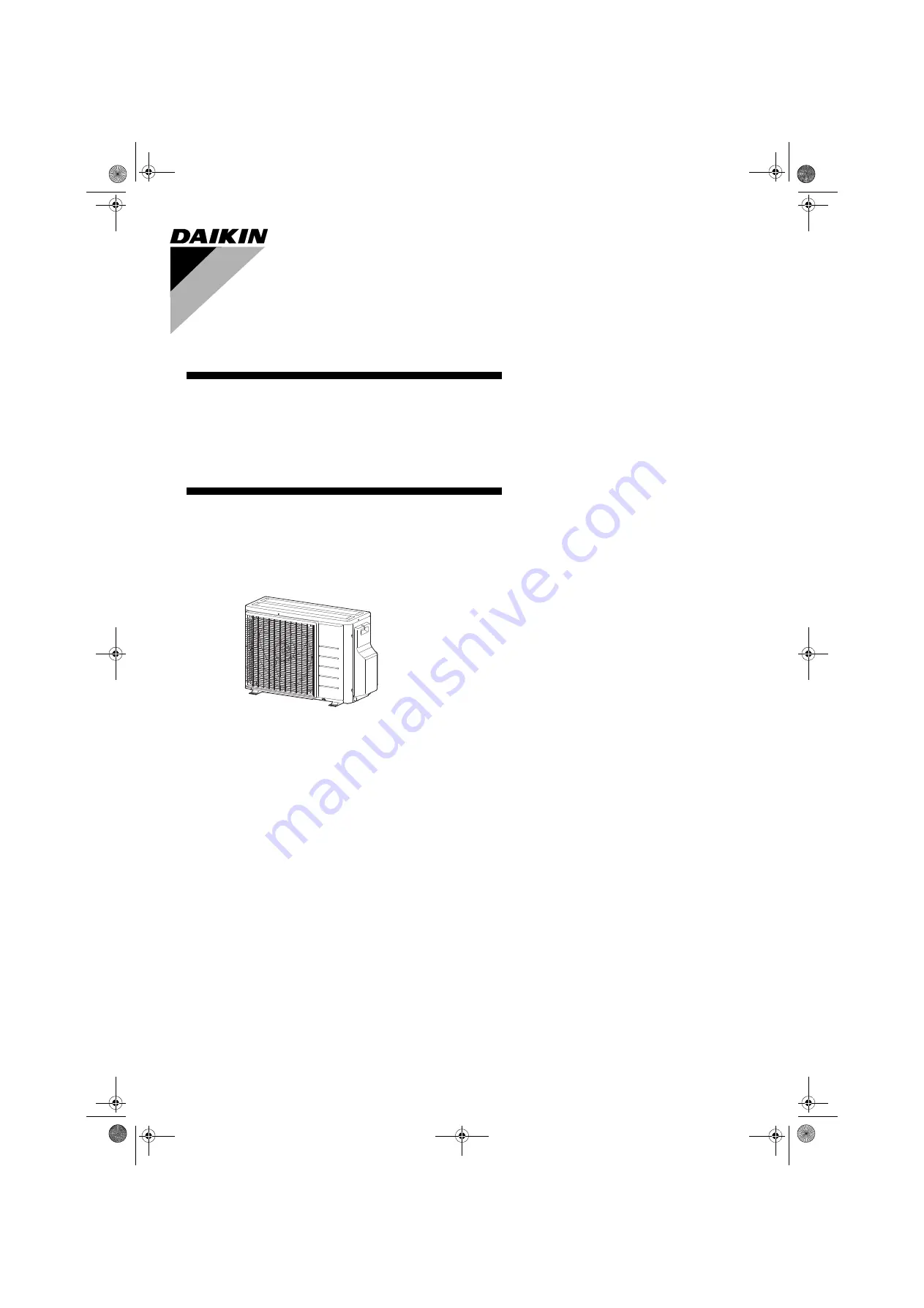
INSTALLATION MANUAL
R32 Split Series
Models 2MXM40M4V1B2MXM50M3V1B92AMXM40M4V1B2AMXM50M4V1B2AMXF40A2V1B2AMXF50A2V1B
3PEN423316-4P.book Page 1 Wednesday, January 16, 2019 11:27 AM
Page 1: ...INSTALLATION MANUAL R32 Split Series Models 2MXM40M4V1B 2MXM50M3V1B9 2AMXM40M4V1B 2AMXM50M4V1B 2AMXF40A2V1B 2AMXF50A2V1B 3PEN423316 4P book Page 1 Wednesday January 16 2019 11 27 AM ...
Page 2: ... positivamente da B secondo il Certificato C 07 Σημείωση όπως καθορίζεται στο A και κρίνεται θετικά από το B σύμφωνα με το Πιστοποιητικό C 08 Nota tal como estabelecido em A e com o parecer positivo de B de acordo com o Certificado C 09 Примечание как указано в A и в соответствии с положительным решением B согласно Свидетельству C 10 Bemærk som anført i A og positivt vurderet af B i henhold til Ce...
Page 3: ...ato positivamente da B secondo il Certificato C 07 Σημείωση όπως καθορίζεται στο A και κρίνεται θετικά από το B σύμφωνα με το Πιστοποιητικό C 08 Nota tal como estabelecido em A e com o parecer positivo de B de acordo com o Certificado C 09 Примечание как указано в A и в соответствии с положительным решением B согласно Свидетельству C 10 Bemærk som anført i A og positivt vurderet af B i henhold til...
Page 4: ... F i henhold til Certifikat G Risikoklasse H Se også næste side 11 enligt A och godkänts av B enligt Certifikatet C i enlighet med den Tekniska Konstruktionsfilen D som positivt intygats av E Fastsatt modul F vilket också framgår av Certifikat G Riskkategori H Se även nästa sida 12 som det fremkommer i A og gjennom positiv bedømmelse av B ifølge Sertifikat C som det fremkommer i den Tekniske Konst...
Page 5: ...мално допустима температура TS TSmin Минимална температура от страната на ниското налягане L C TSmax Температура на насищане съответстваща на максимално допустимото налягане PS M C Охладител N Настройка на предпазното устройство за налягане P bar Фабричен номер и година на производство вижте табелката на модела 22 Maksimalus leistinas slėgis PS K bar Minimali maksimali leistina temperatūra TS TSmi...
Page 6: ...t modul F i henhold til Certifikat G Risikoklasse H Se også næste side 11 enligt A och godkänts av B enligt Certifikatet C i enlighet med den Tekniska Konstruktionsfilen D som positivt intygats av E Fastsatt modul F vilket också framgår av Certifikat G Riskkategori H Se även nästa sida 12 som det fremkommer i A og gjennom positiv bedømmelse av B ifølge Sertifikat C som det fremkommer i den Teknisk...
Page 7: ...лно допустима температура TS TSmin Минимална температура от страната на ниското налягане L C TSmax Температура на насищане съответстваща на максимално допустимото налягане PS M C Охладител N Настройка на предпазното устройство за налягане P bar Фабричен номер и година на производство вижте табелката на модела 22 Maksimalus leistinas slėgis PS K bar Minimali maksimali leistina temperatūra TS TSmin ...
Page 8: ...tions or securing of wires may result in abnormal heat build up or fire When wiring the power supply and connecting the wiring between the indoor and outdoor units position the wires so that the control box cover can be securely fastened Improper positioning of the control box cover may result in electric shocks fire or over heating terminals If the supply cord is damaged it must be replaced by th...
Page 9: ...wrench If the flare nut is too tight it may crack after prolonged use causing refrigerant leakage Make sure to provide for adequate measures in order to prevent that the outdoor unit be used as a shelter by small animals Small animals making contact with electrical parts can cause malfunctions smoke or fire Please instruct the customer to keep the area around the unit clean The temperature of refr...
Page 10: ... place under the unit anything which must be kept away from moisture NOTE Cannot be installed hanging from ceiling or stacked CAUTION When operating the air conditioner in a low outdoor ambient temperature be sure to follow the instructions described below To prevent exposure to wind install the outdoor unit with its suction side facing the wall Never install the outdoor unit at a site where the s...
Page 11: ...tting in between the copper piping and the insulation tube Be sure to do this if the outdoor unit is installed above Cut thermal insulation pipe to an appropriate length and wrap it with tape making sure that no gap is left in the insulation pipe s cut line Wrap the insulation pipe with the finishing tape from bottom to top Refrigerant piping must be protected from physical damage Install a plasti...
Page 12: ... each which are available on the market It is best to screw in the foundation bolts until their ends are 20mm from the foundation surface When using the reducer packing shown above be careful not to overtighten the nut or the smaller pipe may be damaged about 2 3 1 the normal torque Apply a coat of refrigeration oil to the threaded connection port of the outdoor unit where the flare nut comes in U...
Page 13: ...iping is as short as possible Shortest allow able length per room is 3m Piping to each indoor unit 20m max Total length of piping between all units 30m max If the outdoor unit is positioned higher than the indoor units If the outdoor unit is positioned otherwise If lower than one or more indoor units More than 50 More than 100 Side view Direction of air 1200 or less Wall facing one side Top view M...
Page 14: ...hich have been used once already Installation shall be done by an installer the choice of materials and installation shall comply with the applicable legislation In Europe the EN378 is the applicable standard that shall be used Ensure that the field piping and connections are not subjected to stress Align the centres of both flares and tighten the flare nuts 3 or 4 turns by hand Then tighten them ...
Page 15: ... pressure gauge reads 0 1MPa 76cmHg 4 After checking the vacuum close the low pressure and high pressure valves on the gauge manifold and stop the vacuum pump Leave as is for 4 5 minutes and make sure the coupling meter needle does not go back If it does go back this may indicate the presence of moisture or leaking from connecting parts After inspecting all the connection and loosening then retigh...
Page 16: ... label supplied with the product Important information regarding the refrigerant used This product contains fluorinated greenhouse gases Do not vent gases into the atmosphere Refrigerant type GWP value factory refrigerant charge of the product see unit name plate additional refrigerant amount charged in the field total refrigerant charge greenhouse gas emissions of the total refrigerant charge exp...
Page 17: ...ARNING Do not use mineral oil on flared part Prevent mineral oil from getting into the system as this would reduce the lifetime of the units Never use piping which has been used for previous installations Only use parts which are delivered with the unit Never install a dryer to this R32 unit in order to guarantee its lifetime The drying material may dissolve and damage the system Incomplete flarin...
Page 18: ...rm the test operation with the operation mode set to cooling For the test operation procedure read the installation manual attached to the indoor unit and the manual of the remote controller Forced cooling operation will stop automatically after around 30 minutes To stop the operation press the ON OFF button CAUTION If the outside temperature is 10 C or lower the safety device might start preventi...
Page 19: ...e sure to use the round crimp style terminal for connection to the power supply terminal block Place the round crimp style terminals on the wires up to the covered part and secure in place 3 Pull the wire and make sure that it does not disconnect Then fix the wire in place with a wire retainer Room A Room A Room B Outdoor unit Indoor unit Be sure to use the dedicated circuits Safety breaker 16 A E...
Page 20: ...y voltage 2 Reconnecting after check When reconnecting be sure to reconnect everything the same way as it was before LED A MULTIMETER DC VOLTAGE RANGE DB1 AC DC DC S21 RED ROOM B ELECTRONIC EXPANSION VALVE COIL S20 WHITE ROOM A ELECTRONIC EXPANSION VALVE COIL S91 RED LIQUID THERMISTOR LEAD WIRE S40 OL LEAD WIRE HIGH PRESSURE SWITCH S70 FAN MOTOR LEAD WIRE S80 WHITE FOUR WAY VALVE LEAD WIRE S90 THE...
Page 21: ...NITOR GREEN HIGH VOLTAGE HIGH VOLTAGE IES INTELLIGENT EYE SENSOR IPM INTELLIGENT POWER MODULE K R KCR KFR KHuR K M MAGNETIC RELAY L LIVE L COIL L R REACTOR M STEPPER MOTOR M C COMPRESSOR MOTOR M F FAN MOTOR M P DRAIN PUMP MOTOR M S SWING MOTOR MR MRCW MRM MRN MAGNETIC RELAY N NEUTRAL n N NUMBER OF PASSES THROUGH FERRITE CORE PAM PULSE AMPLITUDE MODULATION PCB PRINTED CIRCUIT BOARD PM POWER MODULE ...
Page 22: ...n the side and remove the top plate of the outdoor unit 2 Remove the electric box cover by sliding it being careful not to bend the electric box hook 3 Cut the jumper J23 of the PCB inside 4 Go back through step 2 1 Make sure all components are well secured when doing this CAUTION When returning the electric box cover be careful not to pinch the fan motor lead wire Top plate Electric box cover 1 R...
Page 23: ...it and sets the indoor unit into standby electricity saving mode thus reducing the power consumption of the air conditioner The standby electricity saving function works on the following indoor units CAUTION The standby electricity saving function cannot be used for models other than the specified ones Procedure for turning on standby electricity saving function 1 Check that the main power supply ...
Page 24: ...ectly particularly cleaning of the air filters operation procedures and temperature adjustment Even when the air conditioner is not operating it consumes some electric power If the customer is not going to use the unit soon after it is installed turn off the breaker to avoid wasting electricity If additional refrigerant has been charged because of long piping list the amount added on the nameplate...
Page 25: ...ng Muffler 9 5CuT 9 5CuT 9 5CuT Branch pipe Muffler Gas stop valve Muffler Gas stop valve 9 5CuT 9 5CuT Thermistor gas Thermistor liquid Thermistor gas 6 4CuT 6 4CuT EVA EV B Motor operated valve 9 5CuT 6 4CuT Thermistor liquid Liquid stop valve Liquid stop valve Branch pipe Branch pipe 6 4CuT 6 4CuT Fan motor 9 5CuT Filter Filter 9 5CuT HPS1 9 5CuT Twin branched muffler Field piping Room A Room B...
Page 26: ...3PEN423316 4P book Page 1 Wednesday January 16 2019 11 27 AM ...
Page 27: ...3PEN423316 4P book Page 1 Wednesday January 16 2019 11 27 AM ...
Page 28: ...3P423316 4P 2019 01 Copyright 2019 Daikin 3PEN423316 4P book Page 1 Wednesday January 16 2019 11 27 AM ...