Dahua Video Conference Terminal User
’s Manual
21
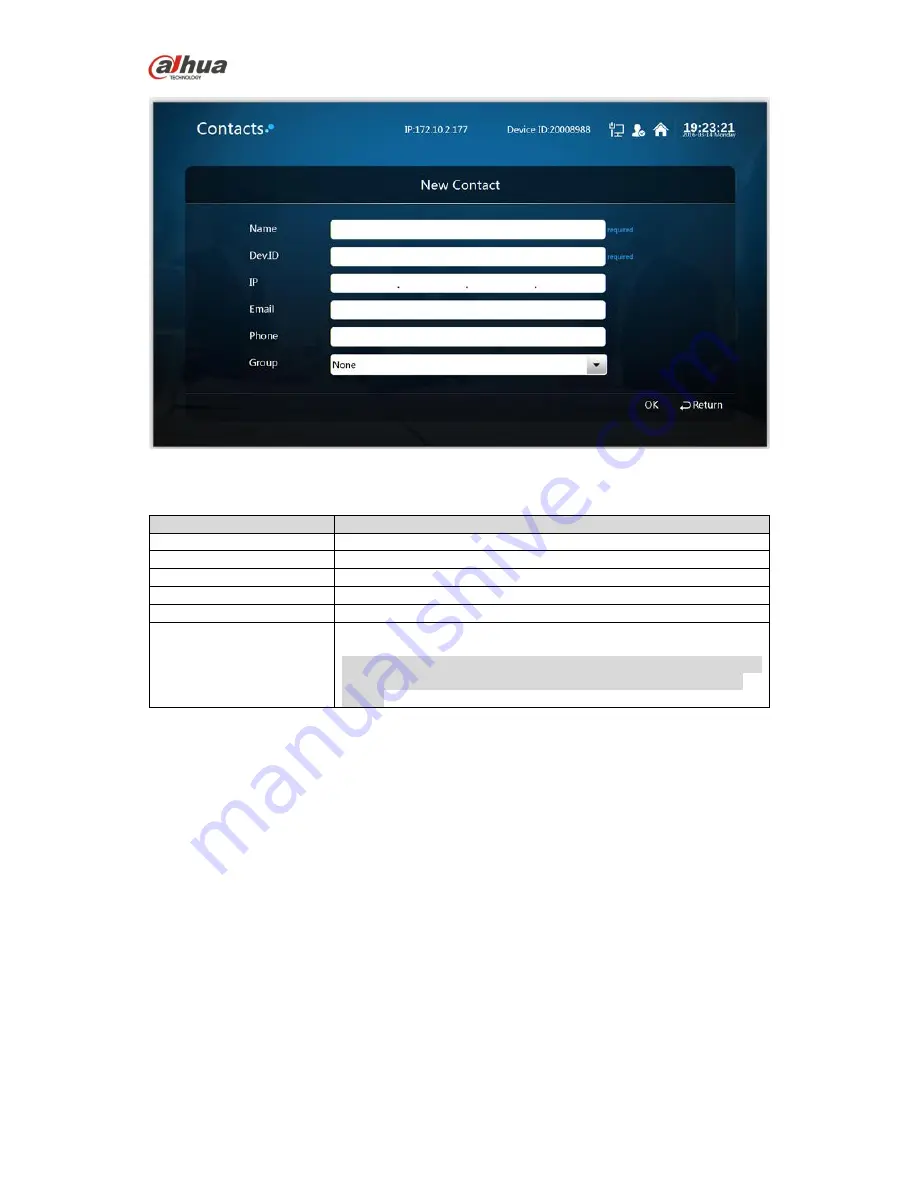
Figure 6-3
Step 2
It is to set interface parameter, please refer to sheet 6-1 for more details about parameter.
Name
Parameter description
Name
It is to add member name.
ID
It is to add member device ID.
IP
It is to add member IP address.
It is to add member email.
Phone
It is to add member phone number.
Group
The group to which the member belongs.
Note:
It needs to establish group first, otherwise, it fails to select in the
box. Please refer to 6.2.3 for more details about creating new
group.
Sheet 6-1
Step 3
Select
“OK” to finish adding contact person.
6.2.2 Delete Contact
Step 1
Select
“Contacts > Contact Person > Delete”. The system displays “Delete” interface, which is
shown in Figure 6-4.