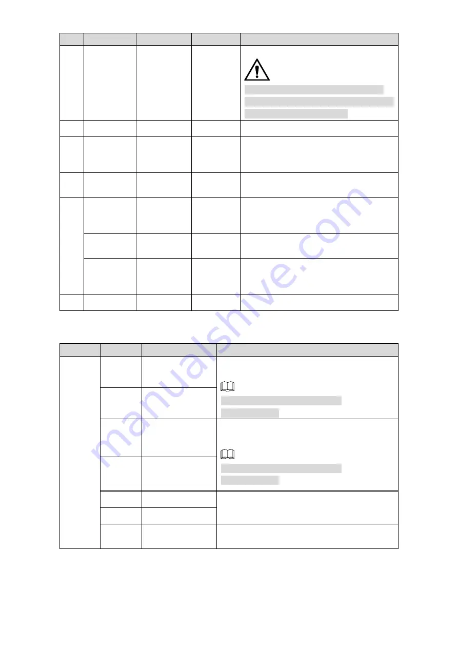
Dahua TPC-BF2221-TB7F8 Quick Start Manual Download Page 14

Design    3 

SN 

Port 

Port Name 

Connector  Function Description 

POWER 

Power input 

port 

— 

Input 24V AC. 


Actual use shall be in accordance with 

device label instruction. Otherwise, it may 

cause damage to the device. 

RS-485 

RS-485 port 

— 

Control external PTZ and so on. 

VIDEO 

OUT 

Analog video 

output 

BNC 

Generally it outputs analog video signal, it 

can  connect  to  TV  monitor  to  check 

image. 

LAN 

Network port 

Ethernet 

port 

Connect to standard Ethernet cable. 

AUDIO IN 

Audio input 

port 

— 

3.5mm Jack port, input audio signal, 

receive analog audio signal from sound 

pick-up and so on. 

AUDIO 

OUT 

Audio output 

port 

— 

3.5mm Jack port, output audio signal to 

earphone and other devices. 

AUDIO 

GND 

Audio 

ground 

terminal 

— 

Ground terminal 

I/O 

I/O port 

— 

Alarm signal input/output. 

Please refer to Table 2-2 for introduction of I/O port. 

Table 2-2 I/O port description 

Port 

Color 

Cable port name 

Function description 

I/O port 

Blue 

ALARM_OUT1 

Alarm output port1, output alarm signal to alarm 

device. 


Use ALARM_OUT1 together with 

ALARM_COM1. 

Green 

ALARM_COM1 

Black 

ALARM_OUT2 

Alarm output port2, output alarm signal to alarm 

device. 


Use ALARM_OUT2 together with 

ALARM_COM2. 

Pink 

ALARM_COM2 

Red 

ALARM_IN1 

Alarm input ports; receive the on-off signal of 

external alarm source. 

Brown 

ALARM_IN2 

Yellow 

&Green 

ALM_IN_GND 

Ground terminal. 

Summary of Contents for TPC-BF2221-TB7F8

Page 1: ...Thermal Hybrid Network Bullet Camera Quick Start Guide V1 0 1...

Page 2: ...uide may cause harmful interference to radio communication For class A device these limits are designed to provide reasonable protection against harmful interference in a commercial environment Operat...

Page 3: ...u solve a problem or save you time NOTE Provides additional information as the emphasis and supplement to the text Revision History No Version Revision Content Release Date 1 V1 0 1 Update screenshot...

Page 4: ...notice The product updates might cause some differences between the actual product and the Guide Please contact the customer service for the latest program and supplementary documentation There still...

Page 5: ...power supply is correct before operating the device Use power supply conforming to SELV requirements and power the camera in the rated voltage conforming to Limited Power Source in IEC60950 1 And ref...

Page 6: ...dismantle the device there is no part which can be repaired by users themselves It may cause water leakage or bad image for the device if it is dismantled unprofessionally It is recommended to use the...

Page 7: ...trol cabinet Please cut off power before device maintenance and overhaul It is prohibited to open the cover with power on in the explosion environment Please make sure all the explosionproof component...

Page 8: ...e system is equipped with the latest security patches and fixes When the equipment is connected to the public network it is recommended to enable the auto check for updates function to obtain timely i...

Page 9: ...ons to them 10 Disable Unnecessary Services and Choose Secure Modes If not needed it is recommended to turn off some services such as SNMP SMTP UPnP etc to reduce risks If necessary it is highly recom...

Page 10: ...the intranet devices from external network The network should be partitioned and isolated according to the actual network needs If there are no communication requirements between two sub networks it...

Page 11: ...able 2 2 2 3 General Configuration 4 Initializing Camera 4 3 1 Modifying IP Address 5 3 2 Live Video 5 3 3 4 Installation 7 Cable Preparation 7 4 1 Installing Camera 8 4 2 4 2 1 Optional Installing SD...

Page 12: ...hecklist and check the package If you find device damage or any loss contact the after sales service Checklist Figure 1 1 Table 1 1 Checklist description No Name No Name No Name 1 Camera 2 Power cable...

Page 13: ...bles 2 2 Cable type might vary with different cameras and the actual product shall prevail Cable ports Figure 2 2 Please refer to Table 2 1 for more details about the cable function Table 2 1 Cable po...

Page 14: ...und pick up and so on AUDIO OUT Audio output port 3 5mm Jack port output audio signal to earphone and other devices AUDIO GND Audio ground terminal Ground terminal 6 I O I O port Alarm signal input ou...

Page 15: ...by default and your PC s IP address are in the same network segment Open IE browser input camera default IP address in the address bar and then press Step 1 Enter The factory default IP address is 192...

Page 16: ...ect Setup Network TCP IP and the system will display the interface of TCP IP Step 2 which is shown in Figure 3 2 TCP IP Figure 3 2 Configure relevant info of IP address and click Save Step 3 Live Vide...

Page 17: ...to install plug in for the first system login please save and install plug in according to prompt The web interface will refresh automatically after plug in installation is completed then live video...

Page 18: ...Ft 229M RG6 U 1 000Ft 305M RG11 U 1 500Ft 457M Selecting Needed Power Cable It is recommended to implement according to the following requirements when the users need to lengthen the power cable Max T...

Page 19: ...hole Long press the reset button for 4 seconds 5 seconds and you will reset your Camera Please check if the waterproof ring is installed properly before closing the cover otherwise it will affect the...

Page 20: ...Installation 9 4 2 2 Fixing Camera Fixing camera Figure 4 3...

Page 21: ...Then use the insulting tape to seal each port to prevent water leakage 4 2 5 Adjusting Camera Please make sure the adjusting screw is loosened when adjusting device direction and monitoring angle Tigh...

Page 22: ...Installation 11 Adjusting camera Figure 4 5 Table 4 4 Components description No Description No Description 1 Screws for adjusting the camera horizontally 2 Screws for adjusting the camera vertically...

Page 23: ...tput in the alarm setup interface Step 4 and then click Save See Figure 5 1 for the Alarm interface Alarm input is corresponding to the alarm input port of device I O cable It is to set corresponding...

Page 24: ...Alarm 13 Alarm output port ALARM_OUT and ALARM_COM form a switch which can be used to provide alarm output Normally the switch is on and the switch will be off when there is alarm output Alarm output...

Page 25: ...onnect the Camera s ground wire to the tower s ground wire And Make sure that the Camera is over 3 m away from the tower lightning rod s top point Use several strands of copper wire whose total diamet...

Page 26: ...ing protection Appendix table 1 1 Components for lightening protection No Name No Name No Name 1 Video lightning rod 2 Communication lightning rod 3 Power lightning rod 4 Ground wire 5 Steel tube shie...

Reviews: