background image

160 


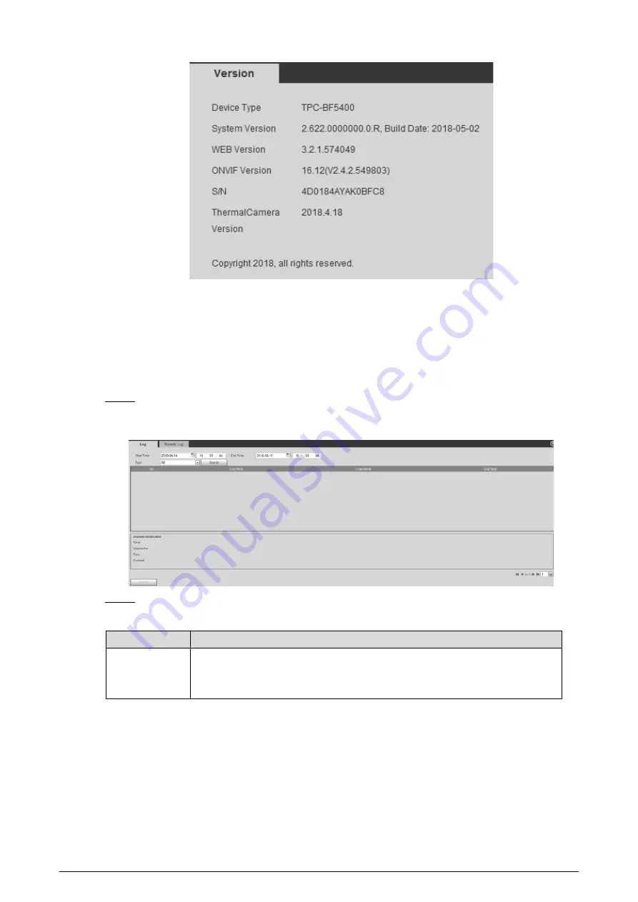
Version 

Figure 5-6


System Log 

5.6

5.6.1


Searching System Logs 

The log type includes "all, system, setting, data, event, record, account and safety." 


Select 

Setting > Information > Log

Step 1

The 

Log

 interface is displayed. See Figure 5-7. 


Log 

Figure 5-7


Set start time and end time, and then select log type. 

Step 2

Table 5-1


Parameter description of system log 

Parameters 

Description 

Start Time 
End Time 

Select a time period which you want to search. 
The earliest start time is January 1, 2000, and the latest end time is December 31, 
2037. 

Summary of Contents for TPC-BF1241-B3F4-S2

Page 1: ...Thermal Network Hybrid Camera Web Operation Manual V1 0 5...

Page 2: ...l hazard which if not avoided could result in slight or moderate injury CAUTION Indicates a potential risk which if not avoided could result in property damage data loss lower performance or unpredict...

Page 3: ...etailed information see the paper manual CD ROM QR code or our official website If there is inconsistency between paper manual and the electronic version the electronic version shall prevail All the d...

Page 4: ...Cameras 19 3 2 2 Speed Dome Cameras Pan Tilt Cameras 23 Playback 35 3 3 3 3 1 Video Playback 35 3 3 2 Picture Playback 40 Reports 42 3 4 Alarm 43 3 5 3 5 1 Introduction to Alarm Types 43 3 5 2 Subscri...

Page 5: ...ing Audio Detection 114 4 5 3 Configuring Temperature Alarm 117 4 5 4 Configuring Alarm 119 4 5 5 Configuring Abnormality 120 Temperature Measuring Settings 124 4 6 4 6 1 Configuring Rules 124 4 6 2 C...

Page 6: ...5 6 1 Searching System Logs 160 5 6 2 Remote View 161 Online User 162 5 7 6 Additional Accessing Methods 163 Accessing through NVR 163 6 1 Accessing through SmartPSS 164 6 2 Cybersecurity Recommendat...

Page 7: ...dings and public area safety Features 1 2 Safe and stable With a full embedded system this Camera can implement all day monitoring in a stable way A long detection distance Wide monitoring range and l...

Page 8: ...functions such as preset tour and pattern You can set a speed dome camera s PTZ functions or a pan tilt camera s PTZ functions such as preset tour pattern horizontal rotation PTZ speed free action bo...

Page 9: ...s Boot up or shut down the intelligent rule display Playback Table 1 2 Description of playback function Function Description Videotaping manually When playing back a video you can record the key infor...

Page 10: ...rd Smoking Detection Available in visible channel When the Camera detects smoking behavior linked measures will be triggered such as Audio Linkage White Light Send Email and Record Boat Detection Avai...

Page 11: ...llowing operations at the same time such as linkage video recording alarm output email delivery PTZ operation and screenshots Abnormality Supports detection of SD card or network abnormality and illeg...

Page 12: ...t map information Then you can do the further analysis through the heat map tools Additional functions Supports enabling or closing temperature testing rules Supports enabling or closing isotherm Supp...

Page 13: ...displayed See Figure 2 1 Initializing camera Figure 2 1 Set the login password for admin account See Table 2 1 Step 2 Table 2 1 Password setting description Parameter Description Password Enter your...

Page 14: ...e 2 2 TCP IP parameters Parameter Description Host Name Give your Camera a name TPCDome for example to help others a router operator for example know the Camera information such as shape information d...

Page 15: ...rd are both admin Select Cameras whose IP address needs to be modified and click the icon indicating that you Step 4 can modify several IP addresses at one time The dialog box of Modify IP Address is...

Page 16: ...phics card Intel HD Graphics Storage 2GB Display 1024 768 Resolution Browser Internet Explorer 9 10 11 Procedure Open browser enter IP address in the address bar and then press Enter Step 1 The login...

Page 17: ...ssword you can use the reserved e mail address to achieve password resetting Open IE browser and type the camera s IP address Then press Enter Step 1 The Thermal Camera interface is displayed See Figu...

Page 18: ...ystem will prompt failure To solve this problem you need to restore your Camera to default settings or wait 24 hours to get a new one Click Next Step 4 The Reset the password 2 2 interface is displaye...

Page 19: ...this channel Double click an image channel and the image channel is displayed in a full video display area Double click the image channel again and the channel will be displayed in a full screen Then...

Page 20: ...t the same time checking real time reports See 3 1 3 Window Adjustment 3 1 2 Function Bar Live view function Figure 3 2 Table 3 2 Live view function description Icon Name Description Regional focus Cl...

Page 21: ...y value The closer AF Peak is to AF Max the better the focusing effect Easy focus will be disabled after five minutes Object Tracking Refer to 4 4 2 Configuring Intelligent Video Surveillance IVS to c...

Page 22: ...e value when the image brightness is proper but contrast is not enough Hue Makes the color deeper or lighter The default value is made by the light sensor and is recommended Saturation Adjusts color d...

Page 23: ...Auto focus Auto focus 3 1 3 4 Optical Axis Calibration Used only for calibrating the Camera lens when the Camera is being debugged in the factory You do not need to operate this function 3 1 3 5 Real...

Page 24: ...the video image and click Then the real time temperature of this spot is displayed See Figure 3 7 Real time spot temperature measuring Figure 3 7 3 1 4 2 Laser Ranging Only Camera with laser ranging c...

Page 25: ...e external PTZ by your bullet camera you need to set the PTZ protocol first and then connect PTZ to your camera Select Setting System Management PTZ Setting Step 1 The PTZ Settings interface is displa...

Page 26: ...igure 3 9 Type the scan number and set the left and right border Step 2 1 Through the direction button move the camera to the left border that you want and click Set Left 2 Through the direction butto...

Page 27: ...Delete Preset to delete preset it in the tour group Type a tour number Click Start to start touring click Stop to end it Step 5 3 2 1 2 4 Configuring Pattern By configuring pattern you can record con...

Page 28: ...on the preview image of the bullet camera Click the PTZ tab and the PTZ control panel is displayed on the right side of the PTZ interface See Figure 3 12 PTZ control panel Figure 3 12 Table 3 6 Parame...

Page 29: ...Figure 3 13 Export or import presets Step 2 Click Export to export presets for backup Click Import to import presets you have already backed up 3 2 2 Speed Dome Cameras Pan Tilt Cameras 3 2 2 1 Confi...

Page 30: ...h under the current situation to the Camera If you need those parameters later you can quickly adopt them and adjust the PTZ and camera to those locations Select Setting PTZ Function Step 1 The Preset...

Page 31: ...add a tour 2 Click Add to add a preset Click repeatedly to add several presets 3 Double click to select a preset And double click to configure the lasting time 4 Double click the touring name that yo...

Page 32: ...camera to a right border you want and click Set Right Limit Select a Scan No and click Start to start scan Step 3 Click Stop to stop the scan 3 2 2 2 4 Configuring Pattern The function of pattern can...

Page 33: ...rt pattern Step 3 Click Stop to stop the pattern 3 2 2 2 5 Configuring Pan Pan function makes your camera rotate horizontally at a speed When you do not have enough cameras to cooperate for a wide vie...

Page 34: ...le or High as the PTZ Speed Select Setting PTZ Function PTZ Speed Step 1 The PTZ Speed interface is displayed See Figure 3 20 PTZ speed Figure 3 20 Select from Low Middle and High The configuration ta...

Page 35: ...t a value of idle time when the time when you do not operate the PTZ is longer than that value the idle motion will be implemented immediately 3 Click Save 3 2 2 2 8 Configuring Power Up If you want t...

Page 36: ...e power is off Click Save Step 4 3 2 2 2 9 Configuring Time Task You can configure a time task and let camera implement certain actions within the period you have set Preparation You have configured p...

Page 37: ...us condition Auto home time Time for your camera to return to its previous condition and continue the time task when the time task is interrupted by human operation 5 Click Period Setting to set the d...

Page 38: ...t PTZ restarts Step 2 3 2 2 2 11 Restoring PTZ to the Default Settings The operations below will delete all the PTZ settings you have configured Please be cautious Select Setting PTZ Function Default...

Page 39: ...default interface Figure 3 25 Click Default Step 2 All your PTZ settings are restored to the default ones 3 2 2 3 Operating PTZ The corresponding protocol settings and function settings have been com...

Page 40: ...nction you can also change the speed of adjusting the PTZ direction zooming changing the focal length and adjusting the aperture 3 Zoom focus and iris Click and the zoom focus and iris value becomes b...

Page 41: ...esets you have already backed up Playback 3 3 Playback of both videos and pictures is supported Functions of different Cameras might vary and the actual product shall prevail Click the Playback tab an...

Page 42: ...and the time period Click any point in the colored area and the playback starts from this moment Each color represents a certain video type and the corresponding relationship is indicated in the recor...

Page 43: ...video playback according to the differences of data sources Data come from SD card or your local storage 3 3 1 3 1 Playing Back Videos in SD Card Select record type in the Data Src bar See Figure 3 30...

Page 44: ...cted date in time order Click any point in the colored area of the time bar See Figure 3 32 The playback starts from that point Time bar Figure 3 32 Click and the video files of the selected date will...

Page 45: ...see 4 1 2 5 Configuring Storage Path Downloading and playing video at the same time is not supported Back Click to go back to the calendar interface 3 3 1 3 2 Playing Back Local Videos In the Data Src...

Page 46: ...a recorded video at the same time Click Save Step 5 The system stops playback and save the edited file under the storage path you have set For detailed operations of setting the storage path see 4 1 2...

Page 47: ...can check and play a snapshot image based on your own needs Select a snapshot type in the selection bar of snapshot type See Figure 3 37 Step 1 Snapshot type selection Figure 3 37 Select jpg in File...

Page 48: ...ary with different browsers and the actual interface shall prevail Back Click to go back to the calendar interface Reports 3 4 You can follow certain rules such as time sequence and check history data...

Page 49: ...ected alarms are triggered the system would record detailed alarm information at the right side of the interface Function of different Cameras might vary and the actual product shall prevail 3 5 1 Int...

Page 50: ...n IVS Alarm is triggered when the set smart plans are triggered You have enabled detection to general behaviors For detailed operations see 4 4 2 Configuring Fire warning Alarm is triggered when fire...

Page 51: ...nd the alarm information will be recorded Click the Alarm tab and the sign disappears If you are at the Alarm interface when the selected alarm is triggered there will be detailed alarm information di...

Page 52: ...1 Configuring Lens 4 1 1 1 Configuring Visible Image 4 1 1 1 1 Configuring Picture Parameters You can configure the picture parameters including brightness contrast saturation Chroma CNT sharpness CN...

Page 53: ...ikely to appear Sharpness CNT The bigger the value the stronger the sharpness CNT Gamma Changes the picture brightness and improves the picture dynamic range in a non linear way The bigger the value i...

Page 54: ...d Iris Select Manual or Aperture Priority as the Mode Then you can configure the iris parameter Exposure Comp Select Manual Aperture Priority or Shutter Priority as the Mode Then you can configure the...

Page 55: ...ht be a few seconds of video loss when the Camera is switching to WDR mode from other modes Table 4 3 Backlight mode description Backlight Mode Description BLC The system adjusts exposure according to...

Page 56: ...on Manual Configure red and blue gain manually the system auto compensates WB according to color temperature Natural The system auto compensates WB to environments without artificial light to ensure c...

Page 57: ...profile management configuration Color The system displays color image Auto The system switches between color and black and white display according to the actual condition B W The system displays blac...

Page 58: ...ly This is called Semi Auto Pressing the focusing button implementing the zooming operation enabling preset or three dimensional positioning and PTZ s rotation will all make the camera focus again aut...

Page 59: ...7 Defogging settings description Defogging Settings Description Auto The system adjusts image clarity according to the actual condition Manual Adjust image clarity manually Off Defogging function disa...

Page 60: ...cific scenario where you use the camera including indoor scenario outdoor scenario and adaptive scenario You can choose a scenario you need and configure and check the scenario Select Setting Camera C...

Page 61: ...4 9 Select the duplicate frame and set the frequently used video parameter as the user defined scene Or you can select the default scene and set the display of the thermal image Low Dynamic Thermal im...

Page 62: ...s mainly represented as brown Brighter when the temperature is higher Boulder Color is concentrated on the range of purple red yellow green blue More purple when the temperature is lower and bluer whe...

Page 63: ...ter the noise reduction but the image will be less clear Gain settings Auto Gain The larger the gain value the more unstable the image Balanced Gain The larger the district the bigger the contrast Gai...

Page 64: ...0 and18 00 24 00 as night System works under corresponding configuration in different time Switching based on time Figure 4 12 Click Save Step 3 4 1 2 Configuring Video Parameters 4 1 2 1 Configuring...

Page 65: ...PS is the clearer and smoother the video will be Bit rate You can select bit rate type Fixed the bit rate changes little and keeps close to the set bit rate value Changeable the bit rate changes as mo...

Page 66: ...watermark Watermark character The default character is Digital CCTV You can configure at most 128 watermark characters which are composed of number letter underline and dash Click Save Step 3 4 1 2 2...

Page 67: ...Select Setting Camera Video Overlay Step 1 The Overlay interface is displayed Click Privacy Masking Step 2 The Privacy Masking interface is displayed See Figure 4 15 Privacy masking interface Figure 4...

Page 68: ...the box s location Click Save Step 4 4 1 2 3 3 Configuring Time Title You can enable this function if you need to display time on the video image Select Setting Camera Video Overlay Step 1 The Overlay...

Page 69: ...OSD Info Step 2 The OSD Info interface is displayed See Figure 4 18 OSD Info Figure 4 18 Select the Enable check box of Text Overlay and enter text based on your own needs Then Step 3 select the text...

Page 70: ...on and Picture overlay can t work at the same time Select Setting Camera video Overlay Step 1 The Overlay interface is displayed Click the Picture Overlay tab Step 2 The Picture Overlay interface is d...

Page 71: ...nable check box Step 2 Hold the left mouse button to draw a ROI area on video images You can also configure the Step 3 ROI s display quality You can draw at most four ROI areas Click Remove All to del...

Page 72: ...min WebDownload LiveSnapshot is the default path Playback Download Playback download refers to the downloaded video of playback interface C Users admin WebDownload LiveSnapshot is the default path Vid...

Page 73: ...t audio encode mode G 711A G 711Mu and AAC are included The configured audio encode mode applies to audio and intercom Sampling Frequency Audio s sampling frequency 8K and 16K are included Audio in Ty...

Page 74: ...etwork Preparation You have connected the camera to network Procedure Select Setting Network TCP IP Step 1 The TCP IP interface is displayed See Figure 4 24 TCP IP interface Figure 4 24 Configure TCP...

Page 75: ...ss You can type IP address and subnet mask according to your own needs All the IPv6 addresses will be validated so ensure IP address and subnet mask are in the same network segment which means the fro...

Page 76: ...demonstration of configuring IP address with ARP Ping 1 To obtain a free IP address you need to ensure that the Camera and your PC are in the same LAN 2 Get MAC address from the Camera label 3 Open c...

Page 77: ...rameter description Parameter Description Max Connection The maximum number of users web client platform client or mobile phone client that can connect to the Camera simultaneously the value is 10 by...

Page 78: ...So if you require the sub stream of channel 2 from a certain Camera then the URL should be rtsp admin admin 10 12 4 84 554 cam realmonitor channel 2 subtype 1 If user name and password are not needed...

Page 79: ...is displayed See Figure 4 27 PPPoE Figure 4 27 Select the Enable check box and type user name and password Step 2 Click Save Step 3 The successful prompt displays and then the real time WAN IP addres...

Page 80: ...name you registered on the DDNS website User name Enter the user name and password you got from DDNS service provide You need to register an account with user name and password on the DDNS service pro...

Page 81: ...Supports 3 addresses at most Interval Time intervals of sending alarm Emails 0 means there is no interval Set a time interval normally 0s as you want and when alarm video detection or event is trigge...

Page 82: ...0 Select the Enable check box Step 2 Select mode and service name in the port mapping list Step 3 UPnP can be classified as custom mode and default mode Under custom mode you can change external ports...

Page 83: ...gure 4 31 SNMP 2 Figure 4 32 Select the Version check box to enable SNMP Step 2 Configure SNMP parameters See Table 4 17 Step 3 In the Trap Address bar enter the IP address of the PC that has MIB Buil...

Page 84: ...number letter underline and dash to form the name Trap SNMP trap is a SNMP agent which transmits information such as important event or change of state to the administrator Trap address A destination...

Page 85: ...his thermal camera is detected by Bonjour server name you have set will be displayed Bonjour is enabled by default Select Setting Network Bonjour Step 1 The Bonjour interface is displayed See Figure 4...

Page 86: ...st protocol 4 2 10 Configuring Auto Registration In the Auto Register interface you can set an IP address to which the camera will report its location Select Setting Network Auto Register Step 1 The A...

Page 87: ...Code Point there are 64 priority degrees 0 63 of data packets 0 represents the lowest and 63 the highest Based on those differences the 64 priority degrees will be classified as different groups Each...

Page 88: ...m Prio When the camera zooms in or out the visible surveillance image the IR light s brightness will be adjusted automatically Manual Adjust the IR light s brightness manually to realize the best imag...

Page 89: ...op to end it Click Once to get the wiper work for one round 4 3 3 Configuring Fan Select Setting Peripheral Fan Step 1 The Fan interface is displayed See Figure 4 40 Fan Figure 4 40 Configure fan s ru...

Page 90: ...ettings see 4 4 10 Configure Linked Measures Pan Tilt cameras and dome cameras have preset function Bullet cameras don t So whether the interface has preset function varies 4 4 1 Configuring Smart Pla...

Page 91: ...Analysis in scenes with intensive targets changing lighting conditions or small difference between target temperature and scene temperature For thermal channel try not to monitor scenes with glass For...

Page 92: ...Audio Linkage White Light and Relay out Auto Tracking is one of them For example when the rule tripwire detects an object alarm will be triggered 4 4 2 2 1 Tripwire Draw a line on the video image and...

Page 93: ...the default line and click Draw Rule to define lines Draw a line or several connected lines and decide its extending direction and length based on the scene you want to monitor For example to monitor...

Page 94: ...r the lens to track the object To set linked measures such as Audio Linkage and White Light when the tripwire rule Step 5 detects an object see 4 4 10 Configure Linked Measures Click Save Step 6 4 4 2...

Page 95: ...ection and draw the second line to form the pentagon s another edge Continue until you have finished drawing the pentagon Right click to end drawing Note that for the rule tripwire to work out it take...

Page 96: ...Cross Inside as your Rule Type You can select from Enters Exits and Enters Exits Max Target Number Set this parameter when you select Inside or Cross Inside as your Rule Type Set a maximum target num...

Page 97: ...ear the default box and click Draw Rule to define box Based on the scene you want to monitor a pentagon area for example draw a pentagon around the area Draw a line parallel to the pentagon area s one...

Page 98: ...triggered Alarm Track Enable this function and when tripwire is triggered the Camera will use thermal lens or visual lens to track the object Track Time Time for the lens to track the object To set li...

Page 99: ...l to the pentagon area s one edge to form the pentagon s one edge Then along another direction and draw the second line to form the pentagon s another edge Continue until you have finished drawing the...

Page 100: ...pick 3 Click Save of working period Duration Time from when an object is taken away from the rule box to when linked measures such as Audio Linkage White Light and Relay out are triggered Alarm Track...

Page 101: ...obal setup parameters See Table 4 27 Step 4 Table 4 27 Global setup parameters Parameter Description Anti Disturb Enable Select the On check box to enable this function This function is aimed at elimi...

Page 102: ...ou have set this object can be detected and an alarm is triggered Click Save Step 5 4 4 3 Call Detection Configure call detection to help you monitor the calling behavior at locations such as gas stat...

Page 103: ...u might need to firstly click to disable the corresponding IVS function Click Step 3 to enable Call Detection The icon turns into Click Save Step 4 4 4 3 2 Configure Call Detection Select Setting Smar...

Page 104: ...or a less value If you want to set the sensitivity drag the sliding block next to Sensitivity The larger the Step 6 value is the more sensitive the call detection will be Select Enable to enable the...

Page 105: ...to get the two icons into and to Step 12 disable the corresponding IVS function and Call Detection function Ensure the two functions are disabled Click Save Step 13 4 4 4 2 Configure Smoking Detectio...

Page 106: ...he larger the Step 6 value is the more sensitive the call detection will be Select Enable to enable the preset s call detection Step 7 For linked action settings see 4 4 10 Configure Linked Measures S...

Page 107: ...You might need to firstly click to disable the corresponding IVS function Click Step 3 to enable Call Detection The icon turns into Click Save Step 4 4 4 5 2 Configure Boat Detection Configure tripwir...

Page 108: ...an alarm is triggered 4 4 6 Configuring Fire Warning The system will give out an alarm once a fire is detected Select Setting Smart Thermal Fire Warning Step 1 The Fire Warning interface is displayed...

Page 109: ...ayed In this interface there are seven Settings altogether each of which corresponds to a day in a week Select a Setting you want and there are six periods period1 period6 below for you to pick up 3 C...

Page 110: ...snapshots see 4 1 2 5 Configuring Storage Path To make the snapshot function take effect you need to firstly enable motion detection snapshots See 4 7 1 2 Configuring Snapshot for detailed operations...

Page 111: ...In this interface there are seven Settings altogether each of which corresponds to a day in a week Select a Setting you want and there are six periods period1 period6 below for you to pick up 3 Click...

Page 112: ...pshot Select the Snapshot check box to take a snapshot when there is an alarm To view and set storage path of snapshots see 4 1 2 5 Configuring Storage Path To make the snapshot function take effect y...

Page 113: ...st the box s location Click Save Step 4 4 4 9 Configuring Link Schedule Select Setting Smart Thermal Link Schedule Step 1 The Link Schedule interface is displayed See Figure 4 56 Link schedule Figure...

Page 114: ...function smoking detection for example to work this means perhaps you don t need to pay attention to the scene at 00 00 4 00 click Setting next to Period to define every day in a week 1 Next to Perio...

Page 115: ...this function Alarm Delay Set a length of time for the Camera to delay turning off alarm after an event is actually ended Send Email Select the Send Email check box and an e mail will be delivered to...

Page 116: ...t the object will be detected and an alarm will be triggered Select Setting Event Video Detection Motion Detection Step 1 The Motion Detection interface is displayed See Figure 4 58 Motion detection s...

Page 117: ...ram red line represents motion detection is triggered and green line represents not 3 Click Save Configure motion detection parameters See Table 4 31 Step 4 Table 4 31 Motion detection parameters Para...

Page 118: ...ly ended Send Email Select the Send Email check box and an e mail will be delivered to the Camera user once an alarm is triggered Set your e mail first before enabling the Send Email function See 4 2...

Page 119: ...ce is displayed In this interface there are seven Settings altogether each of which corresponds to a day in a week Select a Setting you want and there are six periods period1 period6 below for you to...

Page 120: ...5 Configuring SMTP for detailed operations PTZ Select the check box of PTZ and select an item from None Preset Tour and Pattern in the Activation bar Once an alarm is triggered your PTZ will execute t...

Page 121: ...on and an alarm will be triggered when the change of sound intensity exceeds the threshold you have set Sensitivity Volume change of input audio can be identified as audio abnormality only when volume...

Page 122: ...e enabled motion detection recording See 4 7 1 1 Configuring Video Recording for detailed operations You have enabled auto recording See 4 7 3 Configuring Record Control Parameters for detailed operat...

Page 123: ...et an alarm condition When the temperature meets the defined alarm condition an alarm is triggered and the linked activity is executed This function is available on select models and the actual interf...

Page 124: ...recording function works You have enabled motion detection recording See 4 7 1 1 Configuring Video Recording for detailed operations You have enabled auto recording See 4 7 3 Configuring Record Contr...

Page 125: ...ers See Table 4 35 Step 3 Table 4 35 Alarm parameters Parameters Description Relay in Select an external alarm Camera Period Define a period during which the alarm settings are active 1 Click Setting...

Page 126: ...ded Send Email Select the Send Email check box and an e mail will be delivered to the Camera user once an alarm is triggered Set your e mail first before enabling the Send Email function See 4 2 5 Con...

Page 127: ...f the free space in the SD card is lower than the set percentage the alarm is triggered Relay out You can connect this relay out port to alarm Cameras such as light and siren When an alarm is triggere...

Page 128: ...enabled auto recording See 4 7 3 Configuring Record Control Parameters for detailed operations Record Delay Set a length of time for the Camera to delay turning off recording after an alarm is ended R...

Page 129: ...enable this function Alarm Delay Set a length of time for the Camera to delay turning off alarm after an event is actually ended Send Email Select the Send Email check box and an e mail will be delive...

Page 130: ...filter the low temperature objects and improve the identification accuracy Click Save Step 4 Temperature Measuring Settings 4 6 Temperature measuring is available on select models and the actual inter...

Page 131: ...u need on the surveillance image Right click to end your drawing Select a rule you have drawn and click Redraw Rule Then you can delete the rule and draw a new one 4 Select the Open Local Config check...

Page 132: ...this value when you select Alarm Results as Slope By temperature slope we mean the temperature difference in each minute Ranges from 600 C min 600 C min Temperature Error Set a temperature error value...

Page 133: ...ndard of triggering an alarm Average temperature Compare average temperatures of two rules Maximum temperature Compare maximum temperatures of two rules Minimum temperature Compare minimum temperature...

Page 134: ...of surveillance images to show change of color between minimum temperature and maximum temperature Select Setting Temperature Global Setup Step 1 The Global Setup interface is displayed See Figure 4 7...

Page 135: ...high temperature mode value ranges from 40 C to 600 C Max Limit Temperature When gain mode is under low temperature mode value ranges from 40 C to 160 C When gain mode is under high temperature mode v...

Page 136: ...ure 4 75 4 6 3 Exporting Heat Map By exporting heat map you can grasp temperature of every pixel on thermal images Select Setting Temperature Heat Map Step 1 The Heat Map interface is displayed See Fi...

Page 137: ...system would not record video or snapshot as scheduled 4 7 1 1 Configuring Video Recording Set video recording covering General Motion and Alarm Select Setting Storage Schedule Record Step 1 The Recor...

Page 138: ...period 4 Click Save The system returns to the Record interface Each color represents a video type Green represents general video recording schedule yellow represents video recording schedule under mot...

Page 139: ...corresponding time period 4 Click Save The system returns to the Snapshot interface Each color matches with a certain Snapshot type Green means General Snapshot yellow means motion detection Snapshot...

Page 140: ...ave them in SD card FTP or NAS Local storage is available only on models that support SD card Select Setting Storage Destination Path Step 1 The Path interface is displayed See Figure 4 82 Path Figure...

Page 141: ...card you need to set and click Hot Swap Then you can pull out the SD card Select SD card you need to set and click Refresh Then the SD card will be formatted Local storage setting Figure 4 83 4 7 2 3...

Page 142: ...ion can be enabled only when NAS has been selected as destination path Select NAS interface and you can save files in NAS server Select Setting Storage Destination NAS Step 1 The NAS interface is disp...

Page 143: ...pre event video Disk Full The recording strategy when the disk is full Stop The system stops recording when the disk is full Overwrite The system overwrites the oldest files and keep recording when th...

Page 144: ...Language Select system language Video Standard Select video standard from PAL and NTSC Click Save Step 3 4 8 1 2 Configuring Date Time You can set Date and Time format Time zone Current Time DST Dayli...

Page 145: ...rver Click Save Step 3 4 8 1 3 Configuring GPS Fill in the camera s GPS information in the web to remind you where your camera locates Also automatically sent to the management platform the GPS inform...

Page 146: ...IP address instead of user name and password Anonymous users only have preview authorities During Anonymous login Click logout and then you can log in with other username 4 8 2 1 Adding a Group You ha...

Page 147: ...r user group to modify group memo User group added Figure 4 92 4 8 2 2 Adding a User You are admin user by default and you can add user delete added users or modify their password Select Setting Syste...

Page 148: ...ority Select authorities as needed It is recommended to give less authority to normal users than premium users Click Save Step 4 The newly added users are displayed in the user list After adding user...

Page 149: ...1 The Username interface is displayed See Figure 4 95 Username Figure 4 95 Click Step 2 The Modify User interface is displayed See Figure 4 96 Modify user 1 Figure 4 96 Select the Modify Password chec...

Page 150: ...t two of the four types capital letter lowercase letter number and special characters Click Save to finish password modification Step 5 4 8 3 Adding ONVIF User Select Setting System Account ONVIF User...

Page 151: ...Authentication Step 1 The RTSP Authentication interface is displayed See Figure 4 100 RTSP authentication Figure 4 100 Select an authentication mode Step 2 Click Save Step 3 4 8 4 2 Configuring IP Fi...

Page 152: ...ter Description IP address IP address you are going to authorize IP segment Start address and end address of the IP segment MAC address MAC address you are going to authorize 4 Click Save Add an IP Ma...

Page 153: ...by default Enable CGI Common Gateway Interface and then you can use your browser to get data from the server Onvif Service Enabled by default Enable Onvif service to connect your Camera to network vi...

Page 154: ...tificates to your Camera you need to install a root certificate to your PC By this your PC will log in the Camera normally through HTTPS and guarantee your data security 4 8 4 4 1 Creating and Install...

Page 155: ...at uses this certificate Organization Unit Name of organization unit that uses this certificate Email Email of a person or a company who uses this certificate 3 Click Create Requests created will be d...

Page 156: ...igure 4 105 2 Click Install Certificate The Certificate Import Wizard interface is displayed See Figure 4 106 Certificate import wizard Figure 4 106 3 Click Next The certificate store selection interf...

Page 157: ...ick Browse and set the Trusted Root Certification Authorities as certificate store 5 Click Next The certificate import completing wizard is displayed See Figure 4 108 Certificate import wizard complet...

Page 158: ...able HTTPS and a prompt that the Camera needs to be rebooted is displayed Step 6 After your Camera reboots type IP address of the Camera in your browser and access the Camera through HTTPS protocol 4...

Page 159: ...ficate password you are to upload Click Upload Step 3 Installation begins After that certificate property will be displayed in the Certificate Installed bar of the HTTPS interface Click Delete near th...

Page 160: ...112 4 Click Install Certificate The Certificate Import Wizard interface is displayed See Figure 4 113 Certificate import wizard Figure 4 113 5 Click Next The certificate store selection interface is d...

Page 161: ...Click Browse and set the trusted root certificate authority as certificate store 7 Click Next The certificate import completing wizard is displayed See Figure 4 115 Certificate import wizard completin...

Page 162: ...ick Save to finish certificate importing Successful import prompt Figure 4 117 10 Click Save to finish installation of root certificate Enable HTTPS and a prompt that the Camera needs to be rebooted i...

Page 163: ...re settings such as time of when to self reboot rebooting Camera manually and deleting files automatically 5 2 1 Rebooting Camera Select Setting System Auto Maintain Step 1 The Auto Maintain interface...

Page 164: ...g Preset Backup Select Setting System Import Export Step 1 The Import Export interface is displayed See Figure 5 3 Import Export Figure 5 3 Import Export files Step 2 Click Export and paths of backing...

Page 165: ...de the system Step 2 File Upgrade 1 Click Browse and upload upgrade file The upgrade file should be a bin file 2 Click Upgrade to start the process Online Upgrade Only when this thermal camera and you...

Page 166: ...ormation Log Step 1 The Log interface is displayed See Figure 5 7 Log Figure 5 7 Set start time and end time and then select log type Step 2 Table 5 1 Parameter description of system log Parameters De...

Page 167: ...es file access file access error and file search User Management Includes log in log out add user delete user modify user add group delete group and modify group Safety Includes password reset and IP...

Page 168: ...to type remote computer s IP address here Online User 5 7 View all the current Web users Select Setting Information Online User and the Online User interface is displayed See Figure 5 10 Online user...

Page 169: ...Setting Camera Registration Step 1 The Remote Log interface is displayed See Figure 6 1 Registration Figure 6 1 Click Search Step 2 After the search the system displays Cameras that have been searche...

Page 170: ...st Figure 6 2 Type the network segment the Camera is in and then click Search Step 2 After the search the system displays Cameras that have been searched Select Cameras whose IP address needs to be mo...

Page 171: ...suggest that you download and use the latest version of client software Nice to have recommendations to improve your equipment network security 1 Physical Protection We suggest that you perform physi...

Page 172: ...d Video Encrypted Transmission If your audio and video data contents are very important or sensitive we recommend that you use encrypted transmission function to reduce the risk of audio and video dat...

Page 173: ...authentication system to reduce the risk of unauthorized access to private networks It is recommended that you enable your device s firewall or blacklist and whitelist feature to reduce the risk that...

Reviews: