background image


10 

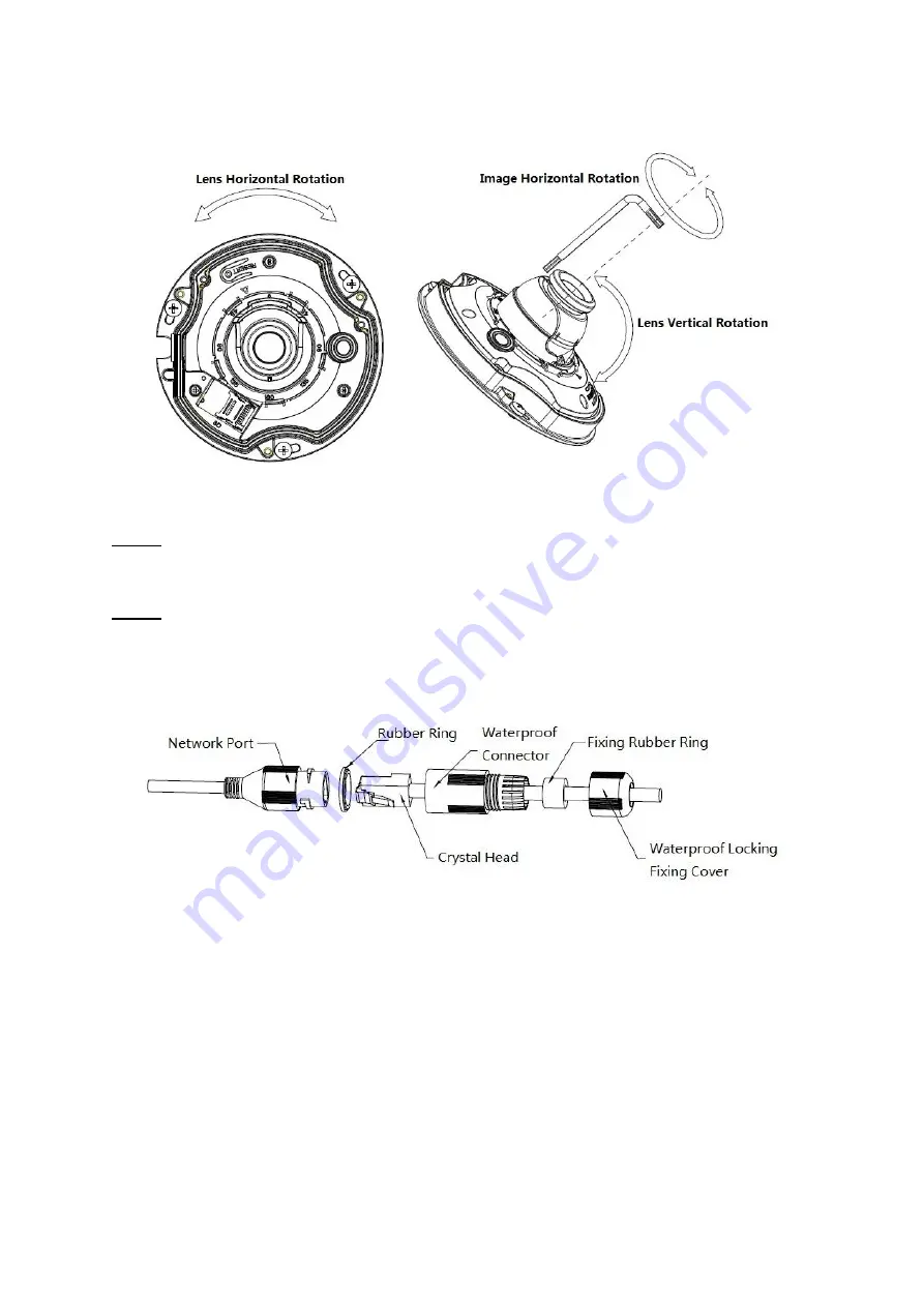
The range of lens adjustment angle: vertical rotation direction (0

°~

+85

°

), image horizontal 

rotation direction (0

°~

+355

°

), image rotation direction (0

°~

+360

°

). 


Figure 2-3 

Step 7  

Hold the dome cover, align it with the cable exit location and make the cover back in position. 

Then use inner hex wrench to fasten three inner hex locking screws to complete installation.  

Step 8  

Waterproof connector installation for network port (Optional); see Figure 2-4 for more details.  

Note:  

Please implement this step if the device is equipped with network port waterproof connector and 

it is used outdoors.  


Figure 2-4 

1.  Keep the convex groove outward and install the rubber ring into the network port, keep the 

smaller hole of the rubber ring outward and install the fixing rubber ring into the main body of 

the waterproof connector.  

2.  Pull the network cable without crystal head through main body of waterproof connector, fixing 

rubber ring and waterproof locking cover, make the crystal head of network cable, and then 

insert it into the network cable.  

3.  Put the main body of waterproof connector on the network port and rotate it clockwise to lock 

the network port and waterproof connector firmly.  

4.  Put the waterproof locking cover on the main body of waterproof connector and rotate it 

clockwise to lock the waterproof connector and waterproof locking cover firmly.  

Summary of Contents for Pro IPC-HDB4231C-AS

Page 1: ...tart Guide Version 1 0 0 Zhejiang Dahua Vision Technology Co LTD Questo manuale d istruzione è fornito da trovaprezzi it Scopri tutte le offerte per Dahua Pro IPC HDB4231C AS o cerca il tuo prodotto tra le migliori offerte di Videosorveglianza ...

Page 2: ...ay result in device damage We assume no liability or responsibility for all the fires or electrical shock caused by improper handling or installation We are not liable for any problems caused by unauthorized modification or attempted repair 2 Environment Please don t aim the device at strong light such as lighting sunlight and so on to focus otherwise it may cause overexposure It is not the device...

Page 3: ...siveness otherwise it will damage the surface coating or reduce the working performance of the device Dome cover is an optical device please don t touch or wipe cover surface directly during installation and use please refer to the following methods to deal with once dirt is found Stained with dirt Use oil free soft brush or hair dries to remove it gently Stained with grease or fingerprint Use sof...

Page 4: ...ide reasonable protection against harmful interference This equipment generates uses and can radiate radio frequency energy and if not installed and used in accordance with the instruction manual may cause harmful interference to radio communication However there is no guarantee that interference will not occur in a particular installation If this equipment does cause harmful interference to radio...

Page 5: ...4 Table of Contents 1 Device Structure 5 1 1 Components 5 1 2 Dimensions 7 2 Installation 8 2 1 Device Installation 8 3 Network Configuration 11 3 1 Modify IP Address 11 3 2 Login WEB Interface 13 ...

Page 6: ...ollowing figures are for reference only which are used to know the device component and cable port function Device component and cable port function may differ according to different models please refer to the actual devices for details Figure 1 1 ...

Page 7: ...d port information Component Component name 1 Device lens 2 X Y Z rotation module 3 Dome enclosure Port Port name Function 4 MIC hole Audio input 5 Network port Connect to standard Ethernet cable provide PoE power supply function 6 Power input port Connect to DC 12V power to input power 7 M12 mobile port Connect to back end device ...

Page 8: ...7 1 2 Dimensions Please refer to the following figure for the dimension information The unit is mm See Figure 1 3 Figure 1 3 ...

Page 9: ...w Step1 Use the inner hex wrench provided to loosen the three inner hexagon screws in the dome cover and then open the cover Step 2 Install SD card Note You need to implement this step if there is a Micro SD card slot and it needs to use Micro SD card for the device Find the SD card slot location which is shown in Figure 2 2 open the upper cover adjust the direction of Micro SD card insert the Mic...

Page 10: ...device cable And then you can pull out the cable from the side exit of cable channel on the pedestal Step 5 Adjust the device installation pedestal to the proper position and then draw the cable through the cable outlet you just dug on the installation surface Align the TOP direction of the device with the installation position map and then align the three screw fixing holes on the device pedestal...

Page 11: ...tdoors Figure 2 4 1 Keep the convex groove outward and install the rubber ring into the network port keep the smaller hole of the rubber ring outward and install the fixing rubber ring into the main body of the waterproof connector 2 Pull the network cable without crystal head through main body of waterproof connector fixing rubber ring and waterproof locking cover make the crystal head of network...

Page 12: ...ce the approach of modifying IP address via Quick Configuration Tool also you can modify the IP address in the network parameters of the WEB interface please refer to the document in the disk WEB Operation Manual for more details Note Currently the quick configuration tool only supports the cameras which apply to the same network segment with computer IP address Step 1 Double click the ConfigTools...

Page 13: ...12 Figure 3 1 Step 3 Modify the camera IP address on the Net interface click Save to finish modification See Figure 3 2 for more details Figure 3 2 ...

Page 14: ...d input the modified camera IP address in the address bar Step 2 The login interface is shown below please input your user name and password Default user name is admin and password is admin respectively click login See Figure 3 3 for more details Figure 3 3 Step 3 Install controls according to the system prompt see Figure 3 4 for the WEB main interface Please modify the administrator password as s...

Page 15: ...n notice If there is any uncertainty or controversy please refer to the final explanation of us Please visit our website or contact your local service engineer for more information Zhejiang Dahua Vision Technology Co Ltd Address No 1199 Bin an Road Binjiang District Hangzhou PRC Postcode 310053 Tel 86 571 87688883 Fax 86 571 87688815 Email overseas dahuatech com Website www dahuasecurity com ...

Reviews: