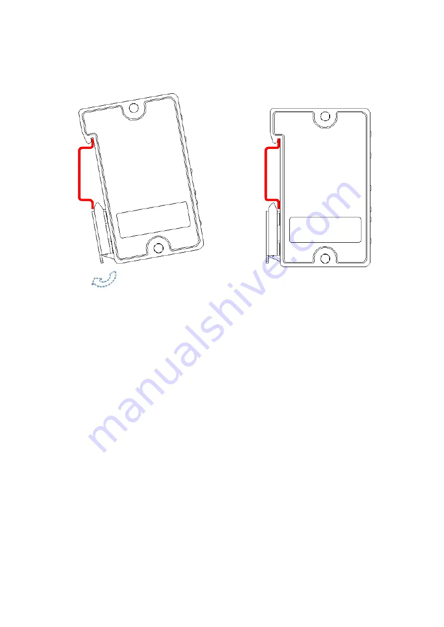
2. The DIN rail mounting is shown in Figure 3-2.
Figure 3-2
Page 1: ...PoE Extender User s Manual V1 0 3...
Page 2: ...r quilt Do not block air vent of the device or ventilation around the device Otherwise temperature in device will rise and may cause fire Do not place any object on the device Do not disassemble the d...
Page 3: ...2 1 Appearance Port 4 Front panel 4 3 Installation Guide 5 3 1 Install Device 5 PoE Extender supports two installation modes which are junction box internal mounting and DIN rail mounting 5 1 The junc...
Page 4: ...1 RJ45 10 100M PoE power supply input 1 RJ45 10 100M supply power for IP Cam 1 RJ45 10 100M supply power for the next extender Cooperate with High PoE Midspan PFT1200 able to cascade level 2 PoE Exte...
Page 5: ...Link status green indicator shows network access Act status OUT 1 10 100M RJ45 port PoE power supply port used to supply power for the next PoE Extender yellow indicator shows Internet access Link st...
Page 6: ...ation Guide 3 1 Install Device PoE Extender supports two installation modes which are junction box internal mounting and DIN rail mounting 1 The junction box internal mounting is shown in Figure 3 1 F...
Page 7: ...2 The DIN rail mounting is shown in Figure 3 2 Figure 3 2...
Page 8: ...und in user interface All the designs and software here are subject to change without prior written notice All trademarks and registered trademarks are the properties of their respective owners If the...