background image


2 Port and Indicator 

2.1 Front Panel 

The following figures are for reference only, and might differ from the actual product. 

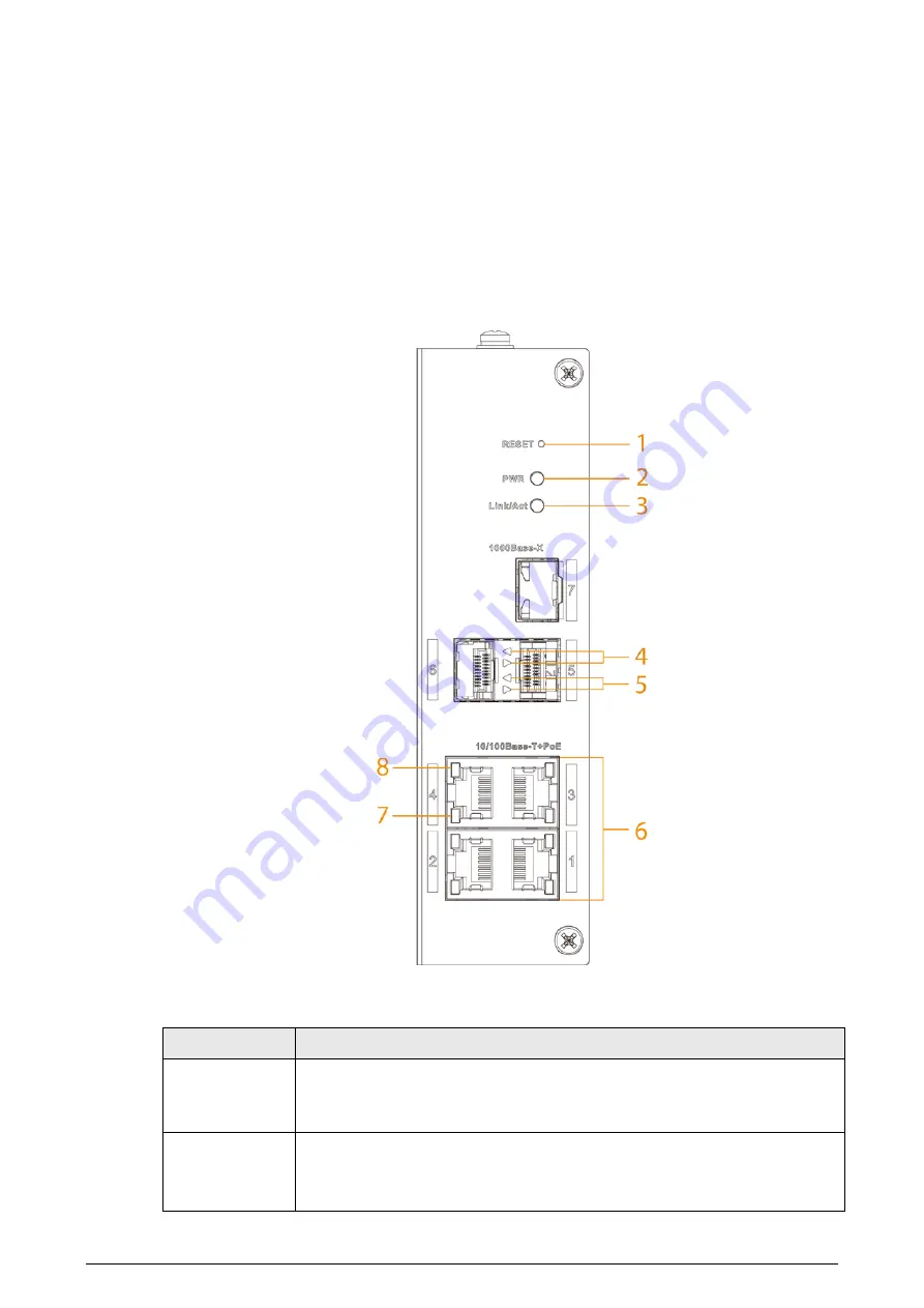
Figure 2-1 Front panel 


The following are all the ports and indicators on the front panel of the Device. 

Table 2-1 Description of front panel 

No. 

Description 

Reset button. 
Press and hold it for more than 5 s, and release after the panel status 

indicators are all on to restore the Device to default settings. 

Power Indicator. 

  On: Power on. 

  Off: Power off. 

Summary of Contents for PFS4307-4ET-96

Page 1: ...Hardened Managed Switch Quick Start Guide V1 0 1 ...

Page 2: ...ne 2022 V1 0 0 First release February 2022 Privacy Protection Notice As the device user or data controller you might collect the personal data of others such as their face fingerprints and license plate number You need to be in compliance with your local privacy protection laws and regulations to protect the legitimate rights and interests of other people by implementing measures which include but...

Page 3: ... the functions operations and technical data If there is any doubt or dispute we reserve the right of final explanation Upgrade the reader software or try other mainstream reader software if the manual in PDF format cannot be opened All trademarks registered trademarks and company names in the manual are properties of their respective owners Please visit our website contact the supplier or custome...

Page 4: ...away from dampness dust and soot Put the device in a well ventilated place and do not block its ventilation Use an adapter or cabinet power supply provided by the manufacturer The power supply must conform to the requirements of ES1 in IEC 62368 1 standard and be no higher than PS2 Please note that the power supply requirements are subject to the device label Do not connect the device to two or mo...

Page 5: ...ons Do not drop or splash liquid onto the device and make sure that there is no object filled with liquid on the device to prevent liquid from flowing into it Operating temperature 30 C 22 F to 65 C 149 F This is a class A product In a domestic environment this may cause radio interference in which case you may be required to take adequate measures Do not block the ventilator of the device with ob...

Page 6: ...cator 2 2 1 Front Panel 2 2 2 Side Panel 3 3 Installation 4 4 Wiring 5 4 1 Connecting GND 5 4 2 Connecting Power Cord 5 4 3 Connecting SFP Ethernet Port 6 4 4 Connecting Ethernet Port 8 4 5 Connecting PoE Port 8 5 Quick Operation 9 5 1 Login through Web 9 5 2 Restoring to Factory Settings 9 Appendix Cybersecurity Recommendations 10 ...

Page 7: ...ion to iLinksView the Device can offer multiple working modes and meet different requirements under different scenarios The Device is applicable for use in different scenarios including corridors factories and offices 1 2 Features 4 100 Mbps Ethernet ports and 3 1000 Mbps uplink optical ports All ports meet the requirements of IEEE802 3af and IEEE802 3at standards The red ports also conform to Hi ...

Page 8: ...Front panel The following are all the ports and indicators on the front panel of the Device Table 2 1 Description of front panel No Description 1 Reset button Press and hold it for more than 5 s and release after the panel status indicators are all on to restore the Device to default settings 2 Power Indicator On Power on Off Power off ...

Page 9: ...ted to device Off Not connected to device Flashes Transmitting 1000 Mbps data 6 10 100 Mbps adaptive PoE port 7 Single port connection or data transmission status indicator Link Act On Connected to device Off Not connected to device Flashes Transmitting data 8 Single port PoE status indicator On Powered by PoE Off Not powered by PoE 2 2 Side Panel The following figure is for reference only and mig...

Page 10: ...rail mount Hang the hook on the rail press the Device to make the buckle stuck into the rail The width of the guide rail supported by the Device is 50 mm Figure 3 1 DIN rail Table 3 1 Component description No Description 1 Hook 2 Rail 3 Buckle ...

Page 11: ...nclosure GND with a cross screwdriver Step 2 Connect one end of the GND cable with the cold pressed terminal and fix it on the enclosure GND with the GND screw Step 3 Connect the other end of the GND cable to the ground The sectional area of the GND cable needs to be more than 2 5 mm2 and the GND resistance needs to be less than 4 Ω 4 2 Connecting Power Cord Redundant power input supports two chan...

Page 12: ...e needs to be more than 0 75 mm max sectional area 2 5 mm Step 4 Insert the plug which is connected to power cable back to the corresponding power terminal socket of the Device Step 5 Connect the other end of power cable to the corresponding external power supply system according to the power supply requirement marked on the Device and check if the corresponding power indicator light of the Device...

Page 13: ... optical port directly when the Device is powered on When installing the SFP optical module do not touch the gold finger of the SFP optical module Do not remove the dust plug of the SFP optical module before connecting the optical port Do not directly insert the SFP optical module with the optical fiber inserted into the slot Unplug the optical fiber before installing it Figure 4 3 SFP module stru...

Page 14: ...igure 4 6 Cable connection The cable connection of RJ 45 connector conforms to the standard 568B 1 orange white 2 orange 3 green white 4 blue 5 blue white 6 green 7 brown white 8 brown 4 5 Connecting PoE Port If the terminal device has a PoE port you can directly connect the terminal device PoE port to the switch PoE port through network cable to achieve synchronized network connection and power s...

Page 15: ...admin Password Web admin iLinksView lt_91_il_02_nmp When using the iLinksView to manage the Device make sure that the username and password must be the same as that you have set in the iLinksView otherwise the iLinksView cannot discover the Device 5 2 Restoring to Factory Settings There are two ways to restore the Device to factory settings Press and hold the Reset button for 5 s to restore the De...

Page 16: ... We suggest that you download and use the latest version of client software Nice to have recommendations to improve your device network security 1 Physical Protection We suggest that you perform physical protection to device especially storage devices For example place the device in a special computer room and cabinet and implement well done access control permission and key management to prevent ...

Page 17: ...minder encrypted transmission will cause some loss in transmission efficiency 11 Secure Auditing Check online users we suggest that you check online users regularly to see if the device is logged in without authorization Check device log By viewing the logs you can know the IP addresses that were used to log in to your devices and their key operations 12 Network Log Due to the limited storage capa...

Reviews: