background image


188 


Set preview display mode: On the preview interface, right click mouse, you can view right-click menu. 

Now you can select preview window amount and channel.   


Set channel display mode: On the preview interface, if you want to change channel 1 and channel 16 

position, please right click channel 1 video window and then drag to the channel 16 video window, 

release button, you can change channel 1 and channel 16 position.   


Tour setup: Here you can set preview window channel display mode and interval. Please follow the 

steps listed below.   

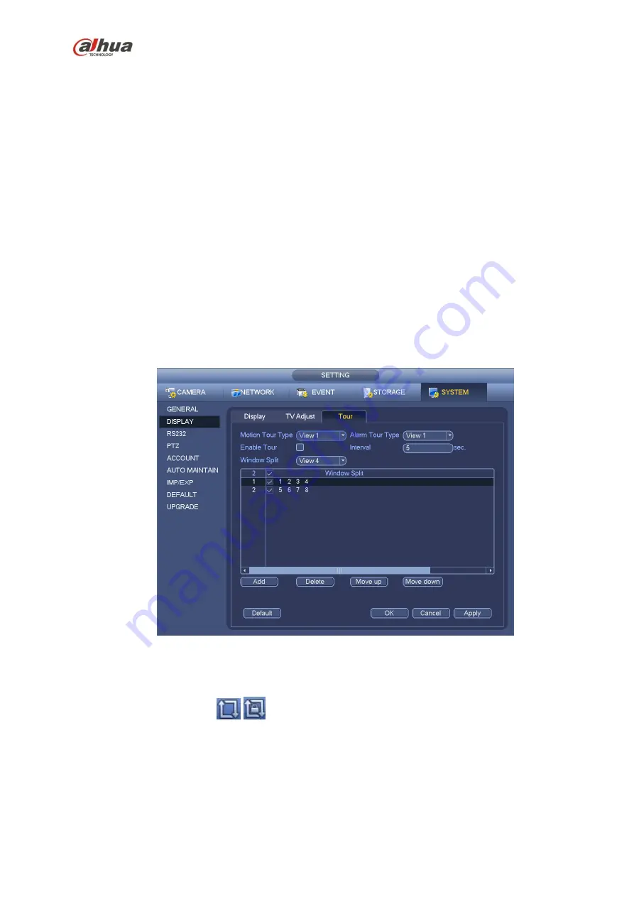
From Main menu->Setting->System->Display->Tour, you can see an interface shown as in Figure 4-40. 

Here you can set tour parameter.   


Enable tour: Check the box here to enable tour function. The general tour supports all types of 

window split mode.   


Interval: Input proper interval value here. The value ranges from 1-120 seconds.   


Motion tour type: System support 1/8-window tour. Please note you need to go to the main 

menu->Setting->Event->Video detect->Motion detect to enable tour function.   


Alarm tour type: System support 1/8-window tour. Please note you need to go to the main 

menu->Setting->Event->Alarm to enable tour function.   


Window split: It is to set window split mode.   


Figure 4-40 

Tips 

On the navigation bar, click 

/

  to enable/disable tour. 

Click Save button to save current setup.   

4.8  Fish eye (Optional)   

Please note this function is for some series only.


4.8.1

  Fish eye de-warp during preview interface 

On the preview interface, select fish eye channel and then right click mouse, you can select fish eye. See 

Summary of Contents for nvr4208-8p

Page 1: ...Dahua Network Video Recorder User s Manual V 2 7 0 ...

Page 2: ... NVR44 44 8P 44 16P Series 31 1 3 17 NVR44 4K Series 33 1 3 18 NVR54 4KS2 54 16P 4KS2 Series 34 1 3 19 NVR48 4K Series 36 1 3 20 NVR58 4KS2 58 16P 4KS2 Series 38 1 3 21 NVR48 48 16P Series 39 1 3 22 NVR72 72 8P Series 41 1 3 23 NVR74 74 8P 74 16P Series 43 1 3 24 NVR78 78 16P 78 RH Series 45 1 3 25 NVR70 70 R Series 47 1 3 26 NVR42V 8P Series 48 1 3 27 NVR41 4KS2 41 P 4KS2 41 8P 4KS2 Series 50 1 3...

Page 3: ...2 2 6 NVR11HS Series 83 2 2 7 NVR21HS S2 21HS P S2 21HS 8P S2 Series 84 2 2 8 NVR41HS W S2 Series 85 2 2 9 NVR22 S2 22 P S2 22 8P S2 Series 86 2 2 10 NVR42 42N 42 P 42 8P 42 16P Series 87 2 2 11 NVR42 4K 52 4KS2 52 8P 4KS2 52 16P 4KS2 Series 90 2 2 12 NVR42 8P 4K Series 91 2 2 13 NVR44 44 8P 44 16P Series 93 2 2 14 NVR44 4K 48 4K 54 4KS2 58 4KS2 54 16P 4KS2 58 16P 4KS2 Series 95 2 2 15 NVR48 48 16...

Page 4: ...52 8P 4KS2 52 16P 4KS2 22 S2 22 P S2 22 8P S2 42 4KS2 42 P 4KS2 42 8P 4KS2 42 16P 4KS2 Series 136 3 3 5 NVR44 44 8P 44 16P 74 74 8P 74 16P 44 4K 54 4KS2 54 16P 4KS2 44 4KS2 44 16P 4KS2 Series 136 3 3 6 NVR48 48 16P NVR78 78 16P 48 4K 58 4KS2 58 16P 4KS2 48 4KS2 48 16P 4KS 2 Series137 3 3 7 NVR78 RH Series 138 3 3 8 NVR70 70 R Series 139 3 3 9 NVR42V 8P Series 140 3 4 CD ROM Installation 140 3 5 Co...

Page 5: ...ies 160 3 5 24 NVR42V 8P Series 161 4 Local Basic Operation 163 4 1 Boot up and Shutdown 163 4 1 1 Boot up 163 4 1 2 Shutdown 163 4 2 Change Reset Password 163 4 2 1 Change Password 163 4 2 2 Reset Password 164 4 3 Startup Wizard 165 4 4 Navigation Bar 169 4 4 1 Main Menu 170 4 4 2 Dual screen operation 170 4 4 3 Output Screen 170 4 4 4 Tour 170 4 4 5 PTZ 170 4 4 6 Color 170 4 4 7 Search 170 4 4 8...

Page 6: ...2 Overlay 199 4 10 1 3 Snapshot 200 4 10 2 Schedule 201 4 10 2 1 Schedule Record 201 4 10 2 2 Schedule Snapshot 204 4 10 3 Motion detect record snapshot 206 4 10 3 1 Motion detect record 206 4 10 3 2 Motion Detect Snapshot 208 4 10 4 Alarm Record Snapshot 209 4 10 4 1 Alarm Record 209 4 10 4 2 Alarm Snapshot 210 4 10 5 Manual Record Snapshot 211 4 10 5 1 Manual Record 211 4 10 5 2 Manual Snapshot ...

Page 7: ...al 240 4 13 5 Alarm output 241 4 13 6 Alarm Setup 242 4 13 7 Abnormality 247 4 14 Network 249 4 14 1 1 TCP IP 249 4 14 1 2 Connection 251 4 14 1 3 WIFI AP 252 4 14 1 3 1 WIFI AP 252 4 14 1 3 2 Advanced 253 4 14 1 4 WIFI 254 4 14 1 5 3G 255 4 14 1 6 PPPoE 256 4 14 1 7 DDNS 257 4 14 1 8 UPnP 259 4 14 1 9 IP Filter 260 4 14 1 10 Email 262 4 14 1 11 FTP 263 4 14 1 12 SNMP 265 4 14 1 13 Multicast 265 4...

Page 8: ... 288 4 17 1 5 1 Device Status 288 4 17 1 5 2 Firmware 289 4 17 2 Log 290 4 17 3 Voice 291 4 17 3 1 1 File Manage 291 4 17 3 1 2 Schedule 292 4 17 4 Account 292 4 17 4 1 1 Add User 294 4 17 4 1 2 Modify user 296 4 17 4 1 3 Change Password 296 4 17 4 1 4 Add Modify Group 296 4 17 4 1 5 Security Question 298 4 17 5 Update 298 4 17 5 1 Local Update 298 4 17 5 2 Uboot 299 4 17 6 Default 299 4 17 7 RS23...

Page 9: ... 2 Advanced 323 5 8 2 4 WIFI 324 5 8 2 5 3G 325 5 8 2 5 1 CDMA GPRS 325 5 8 2 5 2 Mobile 326 5 8 2 6 PPPoE 327 5 8 2 7 DDNS 327 5 8 2 8 IP filter 328 5 8 2 9 Email 329 5 8 2 10 UPnP 330 5 8 2 11 SNMP 331 5 8 2 12 Multicast 332 5 8 2 13 Auto Register 333 5 8 2 14 Alarm Centre 333 5 8 2 15 HTTPS 334 5 8 2 15 1 Create Server Certificate 334 5 8 2 15 2 Download root certificate 335 5 8 2 15 3 View and...

Page 10: ...P 360 5 8 4 3 Record Control 361 5 8 4 4 RAID Manager 362 5 8 4 4 1 RAID Config 362 5 8 4 4 2 Hotspare disks 362 5 8 4 5 Storage 363 5 8 4 5 1 Main Stream 363 5 8 4 5 2 Sub Stream 363 5 8 4 5 3 Snapshot 364 5 8 5 Setting 364 5 8 5 1 General 364 5 8 5 1 1 General 364 5 8 5 1 2 Date and time 365 5 8 5 1 3 Holiday Setup 366 5 8 5 2 Account 366 5 8 5 2 1 User name 367 5 8 5 2 2 Group 368 5 8 5 3 Displ...

Page 11: ...379 5 10 4 Download 380 5 10 5 Load more 380 5 10 5 1 Download By File 380 5 10 5 2 Download by Time 381 5 10 5 3 Watermark 382 5 11 Alarm 382 5 12 Log out 383 5 13 Un install Web Control 384 6 Glossary 385 7 FAQ 386 8 Appendix A HDD Capacity Calculation 391 9 Appendix B Compatible Network Camera List 392 ...

Page 12: ...o recorder This user s manual is designed to be a reference tool for your system Please open the accessory bag to check the items one by one in accordance with the list below Contact your local retailer ASAP if something is missing or damaged in the bag ...

Page 13: ...e explosive substances and etc This series product shall be transported storage and used in the specified environments Environment which needs to comply with the following conditions The function of the ITE being investigated to IEC 60950 1 is considered not likely to require connection to an Ethernet network with outside plant routing including campus environment The installation instructions cle...

Page 14: ...gital device pursuant to Part 15 of the FCC Rules These limits are designed to provide reasonable protection against harmful interference in a residential installation This equipment generates uses and can radiate radio frequency energy and if not installed and used in accordance with the instructions may cause harmful interference to radio communications However there is no guarantee that interfe...

Page 15: ... be provided with antenna installation instructions and transmitter operating conditions for satisfying RF exposure compliance IEEE 802 11b 802 11g or 802 11n 20MHz operation of this product in the U S A is firmware limited to channels 1 through 11 IEEE 802 11n 40MHz operation of this product in the U S A is firmware limited to channels 3 through 9 ...

Page 16: ...eries support TV VGA HDMI output at the same time Short cut menu when preview Support popular PTZ decoder control protocols Support preset tour and pattern Playback Support each channel real time record independently and at the same time it can support search forward play network monitor record search download and etc Support various playback modes slow play fast play backward play and frame by fr...

Page 17: ...ed files can be saved in network storage server peripheral USB2 0 device burner and etc Network Management Supervise NVR configuration and control power via Ethernet Support management via WEB Peripheral Equipment Management Support peripheral equipment management such as protocol setup and port connection Support transparent data transmission such as RS232 RS 422 RS485 RS 485 Auxiliary Support sw...

Page 18: ... output HDMI 1 ch HDMI output Version number is 1 4 Window Split 1 4 8 window Audio Audio Input N A Audio Output N A Audio Compression Standard G 711a Alarm Alarm Input N A Alarm Output N A Funciton Storage 1 built in 2 5 inch SATA port Multiple Chann el Playback Max 8 channel D1 or 4 channel 720P or 2 channel 1080P playback Port and Indicator RS232 Port N A RS485 Port N A USB Port 2 peripheral US...

Page 19: ...ter power supplying mode DC 48V 1 25A power Power Button N A Power On off Button N A IR Receiver Window N A Clock Built in clock Indicator Light N A General Power Consumption 10W No HDD Working Temperature 10 55 Working Humidity 10 90 Air pressure 86kPa 106kPa Dimension 191 8mm 128 2mm 35 8mm Weight 0 32kg 0 36kg No HDD Installation Mode Desk installation 1 3 2 NVR11 11 P Series Model 11 Series 11...

Page 20: ...pe H 264 MJPEG Decode Capability Max 2 ch 1080P 30fps or 4 ch 720P 30fps or 8 ch D1 30fps Video Video Input 4 8 ch network compression video input Video Output 1 channel VGA analog video output HDMI 1 ch HDMI output Version number is 1 4 Window Split 1 4 8 window Audio Audio Input 1 ch bidirectional talk input Audio Output 1 ch bidirectional talk output Audio Compression Standard G 711a Alarm Alar...

Page 21: ... port PoE N A 4 Power Port 1 power socket Power adapter power supplying mode DC 12V power 1 power socket Power adapter power supplying mode DC 48V power Power Button N A Power On off Button N A IR Receiver Window N A Clock Built in clock Indicator Light One power status indicator light One network status indicator light One HDD status indicator light General Power Consumption 10W No HDD Working Te...

Page 22: ...pports 80Mbps 4 8 ch series product support 4 8 HD connection respectively Total bandwidth supports 80Mbps OS Embedded Linux real time operation system Operation Interface WEB Local GUI Decode Video Decode Type H 264 Decode Capability Max 4 ch 1080P 30fps or 8 ch 720P 30fps or 16 ch D1 30fps Video Video Input 4 8 16 ch network compression video input 4 8 ch network compression video input Video Ou...

Page 23: ...le Chann el Playback Max 16 channel D1 or 8 channel 720P or 4 channel 1080P playback Port and Indicator RS232 Port N A RS485 Port N A USB Port 2 peripheral USB2 0 ports Network Connection 1 RJ45 10 100Mbps self adaptive Ethernet port PoE N A 4 8 Power Port 1 power socket Power adapter power supplying mode DC 12V power 1 power socket Power adapter power supplying mode DC 48V power 1 power socket Po...

Page 24: ...Working Temperature 10 55 Working Humidity 10 90 Air pressure 86kPa 106kPa Dimension 205mm 206 75mm 45 2mm 205mm 206 75mm 45 2mm 425mm 95mm 260 mm Weight 0 5kg 2kg No HDD Installation Mode Desk installation 1 3 4 NVR11H 11H P Series Model 11H Series 11H P Series System System Resources 4 8 ch series product support 4 8 HD connection respectively Total bandwidth supports 28 56Mbps respectively OS E...

Page 25: ...analog video output HDMI 1 ch HDMI output Version number is 1 4 Window Split 1 4 8 window Audio Audio Input 1 ch bidirectional talk input Audio Output 1 ch bidirectional talk output Audio Compression Standard G 711a Alarm Alarm Input N A Alarm Output N A Funciton Storage 1 built in SATA port Multiple Chann el Playback Max 8 channel D1 or 4 channel 720P or 2 channel 1080P playback Port and Indicato...

Page 26: ...apter power supplying mode DC 48V power Power Button N A Power On off Button N A IR Receiver Window N A Clock Built in clock Indicator Light One power status indicator light One network status indicator light One HDD status indicator light General Power Consumption 10W No HDD Working Temperature 10 55 Working Humidity 10 90 Air pressure 86kPa 106kPa Dimension 325mm 250 58mm 51mm Weight 0 5kg 1kg N...

Page 27: ...Video Video Input 4 8 ch network compression video input Video Output 1 channel VGA analog video output HDMI 1 ch HDMI output Version number is 1 4 Window Split 1 4 8 window Audio Audio Input N A Audio Output N A Audio Compression Standard G 711a Alarm Alarm Input N A Alarm Output N A Funciton Storage 1 built in SATA port Multiple Chann el Playback For 8 channel series product Max 2 ch 1080P 30fps...

Page 28: ...er Consumption 10W No HDD Working Temperature 10 55 Working Humidity 10 90 Air pressure 86kPa 106kPa Dimension W D H 260mm 220mm 44mm Weight 0 7kg 0 8kg No HDD Installation Mode Desk installation 1 3 6 NVR21HS S2 21HS P S2 21HS 8P S2 Series Model NVR21HS S2 Series NVR21HS P S2 Series NVR21HS 8P S2 Series System System Resources 4 8 16 ch series product support 4 8 16 HD connection respectively Tot...

Page 29: ...rectional talk input Audio Output 1 ch bidirectional talk output Audio Compression Standard G 711a Alarm Alarm Input N A Alarm Output N A Funciton Storage 1 built in SATA port Multiple Chann el Playback Max 4 channel 1080P or 8 channel 720P or 16 channel D1 playback Port and Indicator RS232 Port N A RS485 Port N A USB Port 2 peripheral USB2 0 ports Network Connection 1 RJ45 10 100Mbps self adaptiv...

Page 30: ...0mm 44mm Weight 0 7kg 0 8kg No HDD Installation Mode Desk installation 1 3 7 NVR41HS W S2 Series Model 41HS W S2 Series System System Resources 4 8 ch series product support 4 8 HD connection respectively Total bandwidth supports 80Mbps OS Embedded Linux real time operation system Operation Interface WEB Local GUI Decode Video Decode Type H 264 MJPEG MPEG4 Decode Capability Max 8 ch 1080P or 4 ch ...

Page 31: ...anel and one at the rear panel Network Connection 1 RJ45 10 100Mbps self adaptive Ethernet port PoE Port N A Power Port 1 power socket Power adapter power supplying mode DC 12V 2A power Power Button N A Power On off Button N A IR Receiver Window N A Clock Built in clock Indicator Light One power status indicator light One network status indicator light One HDD status indicator light General Power ...

Page 32: ... 264 MJPEG MJPEG4 Decode Capability Max 2 ch 5M 25fps or 4 ch 3M 25fps or 4 ch 1080P 30fps or 8 ch 720P 30fs Video Video Input 4 8 16 ch network compression video input Video Output 1 channel VGA analog video output HDMI 1 ch HDMI output Version number is 1 4 Window Split 1 4 8 9 16 window 1 4 window Audio Audio Input 1 ch bidirectional talk input Audio Output 1 ch bidirectional talk output Audio ...

Page 33: ...t in clock Indicator Light One power status indicator light One network status indicator light One HDD status indicator light General Power Consumption 10W No HDD Working Temperature 10 55 Working Humidity 10 90 Air pressure 86kPa 106kPa Dimension 205mm 206 75mm 45 2mm 270mm 204m m 42mm 205mm 206 7 5mm 45 2mm Weight 0 5kg 1kg No HDD Installation Mode Desk installation 1 3 9 NVR41H 41H P 41H 8P Ser...

Page 34: ...irectional talk input Audio Output 1 ch bidirectional talk output Audio Compression Standard G 711a Alarm Alarm Input N A 2 channel Alarm Output N A 2 channel Funciton Storage 1 built in SATA port Multiple Chann el Playback Max 4 channel 1080P playback Port and Indicator RS232 Port N A RS485 Port N A USB Port 2 peripheral USB2 0 ports Network Connection 1 RJ45 10 100Mbps self adaptive Ethernet por...

Page 35: ...ation 1 3 10 NVR22 S2 22 P S2 22 8P S2 Series Model NVR22 S2 Series NVR22 P S2 Series NVR22 8P S2 Series System System Resources 4 8 16 ch series product support 4 8 16 HD connection respectively Total bandwidth supports 80Mbps 4 8 ch series product support 4 8 HD connection respectively Total bandwidth supports 80Mbps OS Embedded Linux real time operation system Operation Interface WEB Local GUI ...

Page 36: ... Max 4 channel 1080P or 8 channel 720P or 16 channel D1 playback Port and Indicator RS232 Port N A RS485 Port N A USB Port 2 peripheral USB2 0 ports Network Connection 1 RJ45 10 100Mbps self adaptive Ethernet port PoE Port N A 4 8 Power Port 1 power socket Power adapter power supplying mode DC 12V power 1 power socket Power adapter power supplying mode DC 48V power 1 power socket Power adapter pow...

Page 37: ...nection respectively Main stream bandwidth supports 40 80 160 160Mbps respectively Operation System Embedded Linux real time operation system Operation Interface WEB Local GUI Decode Video Compres sion H 264 MJPEG MPEG4 Decode Capacity Max supports 16 channel D1 or 8 channel 720P or 4 channel 1080P or 4 3M or 2 5M decode Video Video Input 4 8 16 32 ch network compression video input Video Output 1...

Page 38: ...B2 0 Port Three peripheral USB2 0 ports Network Connecti on 1 RJ45 10 100 1000Mbps self adaptive Ethernet port Power Port One power port power adapter Input DC 12V Power Button One button At the rear panel Power On off Button One button At the front panel IR Receiver Window Support IR remote control Clock Built in clock Indicator Light One power status indicator light One network status indicator ...

Page 39: ...I Decode Video Compres sion H 264 MJPEG MPEG4 Decode Capacity Max supports 16 channel D1 or 8 channel 720P or 4 channel 1080P or 4 3M or 2 5M decode Video Video Input 4 8 16 32 ch network compression video input Video Output 1 channel VGA analog video output HDMI 1 ch HDMI output Version number is 1 4 Window Split 1 4 8 9 16 window Audio Audio Input 1 ch bidirectional talk input Audio Output 1 ch ...

Page 40: ...nput 100 240V 47 63Hz Power Button One button At the rear panel Power On off Button One button At the front panel IR Receiver Window Support IR remote control Clock Built in clock Indicator Light One power status indicator light One network status indicator light One HDD status indicator light General Power Consump tion 30W No HDD Working Temperat ure 10 55 Working Humidity 10 90 Air pressure 86kp...

Page 41: ...VGA analog video output HDMI 1 ch HDMI output Version number is 1 4 Window Split 1 4 8 9 16 window Audio Audio Input 1 ch bidirectional talk input Audio Output 1 ch bidirectional talk output Audio Compres sion G 711a Alarm Alarm Input 4 ch alarm input Alarm Output 2 ch alarm output Function Storage 2 built in SATA ports Multiple c hannel Playback Max 16 channel 720P 8 channel 1080P playback at the...

Page 42: ...ng Temperat ure 10 55 Working Humidity 10 90 Air pressure 86kpa 106kpa Dimensio n 375mm 287mm 52mm Weight 1 5kg 2 5kg No HDD Installatio n Desk installation 1 3 14 NVR42 4K 42 8P 4K Series Model NVR42 4K Series NVR42 8P 4K Series System System Resource s 8 16 32 channel series product support 8 16 32 channel HD connection respectively The main stream bandwidth supports 48 96 192Mbps Operation Syst...

Page 43: ... Output 3 ch alarm output Relay output Relay DC 30V 1A AC 125V 0 5A Activation output Including one controllable DC 12V output Function Storage 2 built in SATA ports Multiple c hannel Playback Max 8 channel 720P 4 channel 1080P 1 channel 4K playback at the same time Port and Indicator RS232 Port One RS232 port to debug transparent COM data RS485 port One RS485 port to control PTZ Support various p...

Page 44: ... 52 16P 4KS2 Series Model NVR52 4KS2 52 8P 4KS2 52 16P 4KS2 Series System System Resource s 8 16 32 64 channel series product support 8 16 32 64 channel HD connection respectively The main stream bandwidth supports 80 160 320 320Mbps Operation System Embedded Linux real time operation system Operation Interface WEB Local GUI Decode Video Compres sion MPEG4 MJPG H 264 H 265 Decode Capacity H 264 H ...

Page 45: ...k at the same time Record Mode Overwrite Backup Mode Flash disk DVD burner Port and Indicator Network Protocol IPv4 IPv6 HTTP UPnP NTP SADP SNMP PPPoE DNS FTP ONVIF Versio n 2 4 PSIA RS232 Port One RS232 port to debug transparent COM data RS485 port One RS485 port to control PTZ Support various protocols USB Port 2 peripheral USB ports One USB2 0 at the front panel and one USB3 0 at the rear panel...

Page 46: ...series 2 60Kg 16 PoE series 2 70Kg Installatio n Desk rack installation 1 3 16 NVR44 44 8P 44 16P Series Model NVR44 Series NVR44 8P Series NVR44 16P Series System System Resource s 8 16 32 channel series product support 8 16 32 channel HD connection respectively The main stream bandwidth supports 200Mbps Operation System Embedded Linux real time operation system Operation Interface WEB Local GUI ...

Page 47: ...e time Port and Indicator RS232 Port One RS232 port to debug transparent COM data RS485 port One RS485 port to control PTZ Support various protocols USB2 0 Port 2 peripheral USB2 0 ports One at the front panel and one at the rear panel Network Connecti on One RJ45 10 100 1000Mbps self adaptive Ethernet port Power Port One power port Input 100 240V 50 60Hz Power Button One button At the rear panel ...

Page 48: ...udio Parameters Audio Input 1 ch MIC bidirectional talk audio input Audio Output 1 ch MIC bidirectional talk audio output Audio Compression Standard G 711a G 711u PCM G726 Video Parameters Video Input 8 16 32 ch network compression video input Video Output 1 channel VGA 2 channel HDMI Video Compression Standard H 264 Window Split Mode The 1st screen 1 4 8 9 16 screen The 2nd screen 1 4 screen Alar...

Page 49: ...485 Port 1 RS485 port To control peripheral PTZ and etc Support various protocols USB Port 1 USB 2 0 port at the front panel and 2 USB3 0 ports at the rear panel HDMI Port 2 HDMI ports Network Port 2 RJ45 10 100 1000Mbps self adaptive Ethernetet ports 2 1000Mbps self adaptive fiber ports Power On off Button One at the rear panel Indicator Light 4 indicator lights 1 system running status indicator ...

Page 50: ...4 channel D1 32 channel 720P 16 channel 1080P 4 channel 4K Functions Record Mode Manual recording motion detection recording schedule recording and alarm recording Priority Manual recording card number recording alarm recording motion detection recording schedule recording Multi Channel Playback Max support 16 channel 1080P playback at the same time Motion Detect Each screen supports 396 330 PAL 2...

Page 51: ...ondensation Dimensions W H D 440 76 411mm Weight No HDD General series 4 30Kg PoE series 4 65Kg Installation Mode Rack desktop 1 3 19 NVR48 4K Series Specifications NVR48 4K System Main Processor Industrial embedded micro processor Operation System Embedded LINUX system System Resources Max 8 channel 1080P connection User Interface WEB local GUI Audio Parameters Audio Input 1 ch MIC bidirectional ...

Page 52: ...eSATA DVD burner Network Function Network Protocol IPv4 IPv6 HTTP UPnP NTP SADP SNMP PPPoE DNS FTP ONVIF PSIA SATA Port 8 SATA Ports eSATA Port 1 eSATA port RS232 Port 1 RS232 port To debug and transmit COM data RS485 Port 1 RS485 port To control peripheral PTZ and etc Support various protocols USB Port 2 USB 2 0 ports at the front panel and 2 USB3 0 ports at the rear panel HDMI Port 2 HDMI ports ...

Page 53: ...I Video Compression Standard H 264 Window Split Mode 1 4 8 9 16 25 36 64 screen Alarm Parameters Alarm Input 16 channel Alarm Output 6 channel relay output Decode Parameters Decode Type MPEG4 MJPG H 264 H 265 Decode Capability H 264 H 265 64 channel D1 32 channel 720P 16 channel 1080P 4 channel 4K Functions Record Mode Manual recording motion detection recording schedule recording and alarm record...

Page 54: ... indicator light 1 HDD indicator light 1 network status indicator light 1 power status indicator light General Parameters Power AC90 264V Power Consumption General series 16 7W No HDD 16 PoE series 17 5W No HDD Working Temperature 10 55 Working Humidity 10 90 No condensation Dimensions W H D 439 7 95 450 8mm Weight No HDD General series 6 55Kg PoE series 7Kg Installation Mode Rack desktop 1 3 21 N...

Page 55: ...Including one controllable DC 12V output Function Storage 4 built in SATA ports 1 external eSATA port Multiple c hannel Playback Max 8 channel 720P 4 channel 1080P playback at the same time Port and Indicator RS232 Port One RS232 port to debug transparent COM data RS485 port One RS485 port to control PTZ Support various protocols USB2 0 Port 3 peripheral USB2 0 ports Two at the front panel and one...

Page 56: ...es NVR72 8P Series System System Resource s 8 16 32 64 channel series product support 8 16 32 64 channel HD connection respectively The main stream bandwidth supports 48 96 192 192Mbps Operation System Embedded Linux real time operation system Operation Interface WEB Local GUI Decode Video Compres sion H 264 MJPEG Decode Capacity Max supports 32 channel D1 or 16 channel 720P or 8 channel 1080P dec...

Page 57: ...232 port to debug transparent COM data RS485 port One RS485 port to control PTZ Support various protocols USB2 0 Port 2 peripheral USB2 0 ports One at the front panel and one at the rear panel Network Connecti on 1 RJ45 10 100Mbps self adaptive Ethernet port Power Port One power port power adapter Input DC 12V One power port Input 100 240V 47 63Hz Power Button One button At the rear panel Power On...

Page 58: ...dth supports 48 96 192 192Mbps Operation System Embedded Linux real time operation system Operation Interface WEB Local GUI Decode Video Compres sion H 264 MJPEG Decode Capacity Max supports 32 channel D1 or 16 channel 720P or 8 channel 1080P decode Video Video Input 8 16 32 64 ch network compression video input Video Output 1 channel VGA analog video output HDMI 1 ch HDMI output Version number is...

Page 59: ...orts One at the front panel and two at the rear panel Network Connecti on Two RJ45 10 100Mbps self adaptive Ethernet ports One RJ45 10 100Mbps self adaptive Ethernet port Power Port One power port Input 100 240V 50 60Hz Power Button One button At the rear panel Power On off Button One button At the front panel IR Receiver Window Support IR remote control Clock Built in clock General Indicator Ligh...

Page 60: ...8 channel 1080P decode Video Video Input 8 16 32 64 ch network compression video input Video Output 1 channel VGA analog video output HDMI 1 ch HDMI output Version number is 1 4 2 ch HDMI output from different video sources Window Split 1 4 8 9 16 25 36 window Audio Audio Input 1 ch bidirectional talk input Audio Output 1 ch bidirectional talk output Audio Compres sion G 711a Alarm Alarm Input 16 ...

Page 61: ... Mbps self adaptive Ethernet port Two RJ45 10 100 1000 Mbps self adaptive Ethernet ports Power Port One power port Input 100 240V 50 60Hz Power Button One button At the rear panel Power On off Button One button At the front panel IR Receiver Window Support IR remote control Clock Built in clock General Indicator Light One power status indicator light One network status indicator light One HDD stat...

Page 62: ...nel VGA analog video output HDMI 1 ch HDMI output 2 ch HDMI output from different video sources Window Split 1 4 8 9 16 25 36 window Audio Audio Input 1 ch bidirectional talk input Audio Output 1 ch bidirectional talk output Audio Compres sion G 711a Alarm Alarm Input 16 ch alarm input Alarm Output 6 ch alarm output Relay output Relay DC 30V 1A AC 125V 0 5A Activation output Including one controll...

Page 63: ...One button At the front panel IR Receiver Window Support IR remote control Clock Built in clock General Indicator Light One power status indicator light One network status indicator light One HDD status indicator light Power Consump tion 35W No HDD Working Temperat ure 10 55 Working Humidity 10 90 Air pressure 86kpa 106kpa Dimensio n 3U case 448mm 490mm 133 2mm Weight 10 5kg 11 5kg No HDD Installa...

Page 64: ...nal talk input Audio Output 1 ch bidirectional talk output Audio Compression G 711a Alarm Alarm Input 2 ch alarm input Alarm Output 1 ch alarm output Functio n Storage 2 built in SATA ports Multiple chann el Playback Max 8 channel 720P 4 channel 1080P playback at the same time Port and Indicato r RS232 Port N A RS485 port N A USB Port Two USB2 0 ports at the front panel and one USB3 0 port at the ...

Page 65: ...nux operation system System Resources 4 8 16 channel series product main stream max support 80 80 80Mbps 4 8 channel series product main stream max support 80 80Mbps 8 16 channel series product main stream max support 80 80Mbps Operation Interface WEB Local GUI Audio Audio Input 1 ch MIC bidirectional talk input Audio Output 1 ch MIC bidirectional talk output Audio Compression Standard G 711a G 71...

Page 66: ...ch video supports PAL 396 22 18 NTSC 330 22 15 detection zones support multiple sensivityly levels Privacy Mask Each channel supports 4 privacy mask zones Record Storage Overwrite Backup Mode USB device DVD burner Port and Indicator Network Protocol IPv4 IPv6 HTTP UPnP NTP SADP SNMP PPPoE DNS FTP ONVI V ersion2 4 PSIA SATA Port One port eSATA Port N A RS232 Port N A RS485 Port N A USB Port 2 perip...

Page 67: ...KS2 Series System Main Processor Industrial embedded micro processor OS Embedded Linux operation system System Resources 4 8 16 channel series product main stream max support 80 80 80Mbps 4 8 channel series product main stream max support 80 80Mbps 8 16 channel series product main stream max support 80 80Mbps Operation Interface WEB Local GUI Audio Audio Input 1 ch MIC bidirectional talk input Aud...

Page 68: ...edule record alarm record The record priority Manual record Alarm record Motion detect record Schedule record Multiple Chann el Playback Max 8 channel 1080P playback Motion Detect Each video supports PAL 396 22 18 NTSC 330 22 15 detection zones support multiple sensivityly levels Privacy Mask Each channel supports 4 privacy mask zones Record Storage Overwrite Backup Mode USB device DVD burner Port...

Page 69: ...ing Humidity 10 90 Air pressure 86kPa 106kPa Dimensions m m 224 9 47 6 260 D H W Weight 1 2Kg No HDD 1 6Kg No HDD 2 1Kg No HDD Installation Mode Desk rack installation 1 3 29 NVR42 4KS2 42 P 4KS2 42 8P 4KS2 42 16P 4KS2 Series Model 42 4KS2 Series 42 P 4KS2 Series 42 8P 4KS2 Series 42 16P 4KS2 Series System Main Processor Industrial embedded micro processor OS Embedded Linux operation system System...

Page 70: ...dow 1 4 window 1 4 8 9 window 1 4 8 9 16 32 window Alarm Alarm Input 4 channel input Alarm Output 2 channel output 1 channel relay output 1 channel 12V control Decode Decode Type MPEG4 MJPG H 264 H 265 Decode Capability H 264 H 265 32 channel D1 or 16 channel 720P or 8 channel 1080P or 2 channel 4K Funciton Record Mode Manual record motion detect record schedule record alarm record The record prio...

Page 71: ...ort VGA Port One port Power Port 1 power socket Power adapter power supplying mode DC 12V 4A power 1 power socket Power adapter power supplying mode DC 48V 96W power 1 power socket Power adapter power supplying mode AC90V 264V 12V5A 52V2 5 A 190W power 1 power socket Power adapter power supplying mode AC90V 264V 12V5A 52V2 5 A 190W power Power On off Button One at the rear panel Indicator Light Fo...

Page 72: ...t Video Output 1 channel VGA video output 1 channel HDMI output Video Compression Standard H 264 Window Split 1 4 8 9 16 32 window Alarm Alarm Input 16 channel input Alarm Output 4 channel output 3 channel relay output 1 channel 12V control Decode Decode Type MPEG4 MJPG H 264 H 265 Decode Capability H 264 H 265 32 channel D1 or 16 channel 720P or 8 channel 1080P or 2 channel 4K Funciton Record Mod...

Page 73: ...thernet ports One Ethernet card One RJ45 10 100 1000Mbps self adaptive Ethernet port PoE Port N A 16 HDMI Port One port VGA Port One port Power Port 1 power socket Power adapter power supplying mode AC90V 264V 12V5 7A 12V0 5A 75W 1 power socket Power adapter power supplying mode AC90V 264V 12V12 5A 53V2 83A Power On off Button One at the rear panel Indicator Light Four indicator lights General Pow...

Page 74: ...hannel VGA video output 1 channel HDMI output Video Compression Standard H 264 Window Split 1 4 8 9 16 32 window Alarm Alarm Input 16 channel input Alarm Output 4 channel output 3 channel relay output 1 channel 12V control Decode Decode Type MPEG4 MJPG H 264 H 265 Decode Capability H 264 H 265 32 channel D1 or 16 channel 720P or 8 channel 1080P or 2 channel 4K Funciton Record Mode Manual record mo...

Page 75: ...0Mbps self adaptive Ethernet ports One Ethernet card One RJ45 10 100 1000Mbps self adaptive Ethernet port PoE Port N A 16 HDMI Port One port VGA Port One port Power Port 1 power socket Power adapter power supplying mode AC90V 264V 12V12 5A 1 power socket Power adapter power supplying mode AC90V 264V 12V12 5A 53V2 83A Power On off Button One at the rear panel Indicator Light Four indicator lights G...

Page 76: ...he following sheet for detailed information SN Name Function 1 HDD status indictor light The red light becomes on when HDD is abnormal 2 Power indicator light The red light becomes on when the power connection is OK 3 Network status indicator light The red light becomes on when the network connection is abnormal 2 1 2 NVR11H 11H P 41H 41H P 41H 8P Series The front panel is shown as in Figure 2 2 F...

Page 77: ...ceive signal from the remote control 2 1 3 NVR11HS Series The front panel is shown as below See Figure 2 3 Figure 2 3 Please refer to the following sheet for detailed information Icon Name Function Network status indicator light The red light becomes on when the network connection is abnormal Power status indicator light The red light becomes on when the power connection is OK HDD status indicator...

Page 78: ...e HDD is malfunction NET Network status indicator light The blue light is on when the network connection is abnormal POWER Power status indicator light The blue light is on when the power connection is OK USB2 0 port Connect to peripheral USB 2 0 storage device mouse burner and etc 2 1 5 NVR41 8P Series The front panel is shown as below See Figure 2 5 Figure 2 5 ...

Page 79: ...er button Power button press this button for three seconds to boot up or shut down NVR Shift Shift In textbox click this button to switch between numeral English Small Capitalized donation and etc Up 1 Down 4 Activate current control modify setup and then move up and down Increase decrease numeral Assistant function such as PTZ menu In text mode input number 1 4 English character G H I Left 2 Righ...

Page 80: ...ious 0 In playback mode playback the previous video In text mode input number 0 Reverse Pau se 6 In normal playback or pause mode click this button to reverse playback In reverse playback click this button to pause playback In text mode input number 6 English character M N O Play Next 9 In playback mode playback the next video In menu setup go to down ward of the dropdown list In text mode input n...

Page 81: ...lue light is on when the network connection is abnormal POWER Power status indicator light The blue light is on when the power connection is OK USB port Connect to peripheral USB storage device mouse and etc 2 1 8 NVR 22 S2 22 P S2 22 8P S2 42 16P 42N 42 4K 42 8P 4K 44 4K 48 4K 52 4KS2 52 8P 4KS2 52 16P 4KS2 54 4KS2 58 4KS2 42 4KS2 42 P 4KS2 42 8P 4KS2 42 16P 4KS2 44 4KS2 44 16P 4KS2 48 4KS2 48 16...

Page 82: ...ection is abnormal POWER Power status indicator light The blue light is on when the power connection is OK USB2 0 port Connect to peripheral USB 2 0 storage device mouse burner and etc 2 1 9 NVR44 44 8P 44 16P 74 74 8P 74 16P Series The front panel is shown as in Figure 2 11 Figure 2 11 Please refer to the following sheet for front panel button information Name Icon Function Power button Power but...

Page 83: ...ck this button to display assistant function PTZ control and image color Backspace function in numeral control or text control press it for 1 5seconds to delete the previous character before the cursor In motion detection setup working with Fn and direction keys to realize setup In text mode click it to switch between numeral English character small capitalized and etc Realize other special functi...

Page 84: ...comes on when system is recording 2 1 10 NVR48 48 16P 78 78 16P Series The Front panel is shown as follows See Figure 2 12 Figure 2 12 Please refer to the following sheet for front panel button information Name Icon Function Power button Power button press this button for three seconds to boot up or shut down NVR Number button 0 9 Input Arabic number Switch channel Input number more than 10 If you...

Page 85: ... the previous character before the cursor In motion detection setup working with Fn and direction keys to realize setup In text mode click it to switch between numeral English character small capitalized and etc In HDD management interface you can click it to switch HDD record information and other information Menu prompt Realize other special functions Fast play Various fast speeds and normal pla...

Page 86: ...4 8 16 channel series product The corresponding channel light becomes on when system is recording For 32 64 channel series product When the light flashes slowly it means the corresponding channel of 1 16 channel is recording now Such as channel 1 When the light flashes fast it means the corresponding channel of 17 32 channel is recording now Such as channel 17 When the light becomes on It means th...

Page 87: ...hen playback click it to restore real time monitor mode Enter ENTER Confirm current operation Go to default button Go to menu Record REC Manually stop start recording working with direction keys or numeral keys to select the recording channel Slow play Multiple slow play speeds or normal playback Assistant Fn One window monitor mode click this button to display assistant function PTZ control and i...

Page 88: ...n key Playback mode counter clockwise to forward and clock wise to backward Jog inner dial Up down direction key Playback mode turn the inner dial to realized frame by frame playback Only applies to some special versions USB port To connect USB storage device USB mouse Remote control receiver IR It is to receive signal from the remote control Remote control indicator light ACT Remote control indic...

Page 89: ...indicator light becomes on once an alarm occurred It becomes on via the software detection The alarm includes local alarm no disk and etc 4 Network indicator light The network indicator light is blue and it flashes when you connect the device to the network 5 USB2 0 port Connect to USB2 0 storage device mouse USB burner and etc 6 16 HDD slot After you remove the front panel you can see there are 1...

Page 90: ...button for three seconds to boot up or shut down NVR Assistant Fn One window monitor mode click this button to display assistant function PTZ control and image color Backspace function in numeral control or text control press it for 1 5 seconds to delete the previous character before the cursor In motion detection setup working with Fn and direction keys to realize setup In text mode click it to s...

Page 91: ...r HDD capacity is below specified threshold value the light becomes red to alert you Network abnormal indicator light Network error occurs or there is no network connection the light becomes red to alert you Alarm indicator light The light becomes on when an alarm occurred 2 2 Rear Panel 2 2 1 NVR100 100 P Series The NVR100 rear panel is shown as below See Figure 2 17 Figure 2 17 The NVR100 P rear...

Page 92: ... VGA video output port Output analog video signal It can connect to the monitor to view analog video Power input port Power socket For NVR100 series input DC 5V 2A For NVR100 P series input DC 48V 1 25A PoE PORT PoE port Built in switch Support PoE function For PoE series product you can use this port to provide power to the network camera 2 2 2 NVR11 11 P Series The NVR11 rear panel is shown as b...

Page 93: ...input port Power socket For NVR11 series input DC 12V 2A For NVR11 P series input DC 48V 1 25A MIC IN Audio input port Bidirectional talk input port It is to receive the analog audio signal output from the devices such as microphone pickup MIC OUT Audio output port Audio output port It is to output the analog audio signal to the devices such as the sound box Bidirectional talk output Audio output ...

Page 94: ...Figure 2 23 Figure 2 23 The NVR41 W rear panel is shown as below See Figure 2 24 Figure 2 24 Please refer to the following sheet for detailed information Port Name Connection Function USB2 0 port USB2 0 port Connect to mouse USB storage device USB burner and etc ...

Page 95: ...ies input DC 48V 2A MIC IN Audio input port Bidirectional talk input port It is to receive the analog audio signal output from the devices such as microphone pickup MIC OUT Audio output port Audio output port It is to output the analog audio signal to the devices such as the sound box Bidirectional talk output Audio output on 1 window video monitor Audio output on 1 window video playback PoE PORT ...

Page 96: ...on audio and video signal output port It transmits uncompressed high definition video and multiple channel data to the HDMI port of the display device HDMI version is 1 4 VGA VGA video output port VGA video output port Output analog video signal It can connect to the monitor to view analog video MIC IN Audio input port Bidirectional talk input port It is to receive the analog audio signal output f...

Page 97: ...ure 2 30 Please refer to the following sheet for detailed information Port Name Connection Function USB2 0 port USB2 0 port Connect to mouse USB storage device USB burner and etc Network port 10M 100Mbps self adaptive Ethernet port Connect to the network cable HDMI High Definition Media Interface High definition audio and video signal output port It transmits uncompressed high definition video and...

Page 98: ...witch Support PoE function For PoE series product you can use this port to provide power to the network camera 2 2 6 NVR11HS Series The series rear panel is shown as below See Figure 2 31 Figure 2 31 Please refer to the following sheet for detailed information Icon Name Function Power input socket Power socket Input DC12V 1 5A Network port 10M 100Mbps self adaptive Ethernet port Connect to the net...

Page 99: ...sheet for detailed information Port Name Connection Function Power input port Power socket For NVR21HS S2 input DC 12V 2A For NVR21HS P S2 input DC 48V 1 25A For NVR21HS 8P S2 input DC 48V 2A Network port 10M 100Mbps self adaptive Ethernet port Connect to the network cable USB port USB port Connect to mouse USB storage device and etc HDMI High Definition Media Interface High definition audio and v...

Page 100: ...udio output port It is to output the analog audio signal to the devices such as the sound box Bidirectional talk output Audio output on 1 window video monitor Audio output on 1 window video playback GND Ground end PoE PORTS PoE port Built in switch Support PoE function For PoE series product you can use this port to provide power to the network camera 2 2 8 NVR41HS W S2 Series The NVR41HS W S2 rea...

Page 101: ... the HDMI port of the display device HDMI version is 1 4 VGA VGA video output port VGA video output port Output analog video signal It can connect to the monitor to view analog video GND Ground end Wireless AP Support wireless hotspot function Use WIFI to connect to the network camera when there is a hotspot 2 2 9 NVR22 S2 22 P S2 22 8P S2 Series The NVR22 S2 series rear panel is shown as below Se...

Page 102: ...ort VGA video output port Output analog video signal It can connect to the monitor to view analog video MIC IN Audio input port Bidirectional talk input port It is to receive the analog audio signal output from the devices such as microphone pickup MIC OUT Audio output port Audio output port It is to output the analog audio signal to the devices such as the sound box Bidirectional talk output Audi...

Page 103: ...e NVR42 16P series rear panel is shown as below See Figure 2 43 Figure 2 43 Please refer to the following sheet for detailed information Name Function Power switch Power on off button Power input port Input DC 12V 5A For NVR42 series product only Switch power port Input DC 48 1 04A For NVR42 P series product only Input AC 100 240V For NVR42 8P 42 16P series product only ...

Page 104: ... make sure there is power to the external alarm device NO Normal open alarm output port C Alarm output public end C1 C2 A RS 485 communication port RS485_A port It is the cable A You can connect to the control devices such as speed dome PTZ B RS485_B It is the cable B You can connect to the control devices such as speed dome PTZ Network port 10M 100M 1000Mbps self adaptive Ethernet port Connect to...

Page 105: ... is shown as below See Figure 2 45 Figure 2 45 The NVR52 16P 4KS2 series rear panel is shown as below See Figure 2 46 Figure 2 46 Please refer to the following sheet for detailed information Icon Port Name Function Network port 10M 100M 1000Mbps self adaptive Ethernet port Connect to the network cable HDMI High Definition Media Interface High definition audio and video signal output port It transm...

Page 106: ... are to receive the signal from the external alarm source There are two types NO normal open NC normal close When your alarm input device is using external power please make sure the device and the NVR have the same ground GND Alarm input ground port NO1 NO3 Alarm output port 1 3 3 groups of alarm output ports Group 1 port NO1 C1 Group 2 port NO2 C2 Group 3 port NO3 C3 Output alarm signal to the a...

Page 107: ...t Connect to mouse USB storage device USB burner and etc RS 232 RS 232 debug COM It is for general COM debug to configure IP address or transfer transparent COM data VGA VGA video output port VGA video output port Output analog video signal It can connect to the monitor to view analog video MIC IN Audio input port Bidirectional talk input port It is to receive the analog audio signal output from t...

Page 108: ...the cable A You can connect to the control devices such as speed dome PTZ B RS485_B It is the cable B You can connect to the control devices such as speed dome PTZ 2 2 13 NVR44 44 8P 44 16P Series The NVR44 series rear panel is shown as below See Figure 2 48 Figure 2 48 The NVR44 8P series rear panel is shown as below See Figure 2 49 Figure 2 49 The NVR44 16P series rear panel is shown as below Se...

Page 109: ... output NO1 NO5 Alarm output port 1 5 5 groups of alarm output ports Group 1 port NO1 C1 Group 2 port NO2 C2 Group 3 port NO3 C3 Group 4 port NO4 C4 Group 5 port NO5 C5 NC5 Output alarm signal to the alarm device Please make sure there is power to the external alarm device NO Normal open alarm output port C Alarm output public end NC Normal close alarm output port C1 C5 NC5 A RS 485 communication ...

Page 110: ... 1 3 VGA VGA video output port VGA video output port Output analog video signal It can connect to the monitor to view analog video PoE PORTS 8 PoE ports Built in Switch Support PoE The 8 PoE ports series products supports total 48V 120W power One PoE port max supports 15W PoE PORTS 16 PoE ports Built in Switch Support PoE The 16 PoE ports series products supports total 150W power One PoE port max ...

Page 111: ... is to output the analog audio signal to the devices such as the sound box Bidirectional talk output Audio output on 1 window video monitor Audio output on 1 window video playback 1 16 Alarm input port 1 16 There are four groups The first group is from port 1 to port 4 the second group is from port 5 to port 8 the third group is from 9 to 12 and the fourth group is from 13 to 16 They are to receiv...

Page 112: ...rovide the power to some peripheral devices such as the camera or the alarm device Please note the supplying power shall be below 1A RS 232 RS232 debug COM It is for general COM debug to configure IP address or transfer transparent COM data VGA VGA video output port VGA video output port Output analog video signal It can connect to the monitor to view analog video PoE PORTS Bult in Switch Support ...

Page 113: ...rmal open NC normal close When your alarm input device is using external power please make sure the device and the NVR have the same ground GND Alarm input ground port NO1 NO5 Alarm output port 1 5 5 groups of alarm output ports Group 1 port NO1 C1 Group 2 port NO2 C2 Group 3 port NO3 C3 Group 4 port NO4 C4 Group 5 port NO5 C5 NC5 Output alarm signal to the alarm device Please make sure there is p...

Page 114: ... video signal output port It transmits uncompressed high definition video and multiple channel data to the HDMI port of the display device HDMI version is 1 3 VGA VGA video output port VGA video output port Output analog video signal It can connect to the monitor to view analog video PoE PORTS 16 PoE ports Built in Switch Support PoE The 16 PoE ports series products supports total 150W power One P...

Page 115: ... first group is from port 1 to port 4 the second group is from port 5 to port 8 They are to receive the signal from the external alarm source There are two types NO normal open NC normal close When your alarm input device is using external power please make sure the device and the NVR have the same ground GND Alarm input ground port NO1 NO3 Alarm output port 1 3 3 groups of alarm output ports Grou...

Page 116: ...iew analog video 1 8 Alarm input port 1 8 There are two groups The first group is from port 1 to port 4 the second group is from port 5 to port 8 They are to receive the signal from the external alarm source There are two types NO normal open NC normal close When your alarm input device is using external power please make sure the device and the NVR have the same ground GND Alarm input ground port...

Page 117: ...t Audio output on 1 window video monitor Audio output on 1 window video playback 2 2 18 NVR74 Series The NVR74 series rear panel is shown as below See Figure 2 57 Figure 2 57 Please refer to the following sheet for detailed information Icon Name Function Power switch Power on off button Power input port Input AC 100 240V MIC IN Audio input port Bidirectional talk input port It is to receive the an...

Page 118: ... the alarm device Please make sure there is power to the external alarm device NO Normal open alarm output port C Alarm output public end NC Normal close alarm output port C1 C5 NC5 A RS 485 communication port RS485_A port It is the cable A You can connect to the control devices such as speed dome PTZ B RS485_B It is the cable B You can connect to the control devices such as speed dome PTZ CTRL 12...

Page 119: ...elow See Figure 2 59 Figure 2 59 Please refer to the following sheet for detailed information Port Name Function Power switch Power on off button Power input port Input AC 100 240V MIC IN Audio input port Bidirectional talk input port It is to receive the analog audio signal output from the devices such as microphone pickup MIC OUT Audio output port Audio output port It is to output the analog aud...

Page 120: ...1 C5 NC5 A RS 485 communication port RS485_A port It is the cable A You can connect to the control devices such as speed dome PTZ B RS485_B It is the cable B You can connect to the control devices such as speed dome PTZ CTRL 12V Controller 12V power output It is to control the on off alarm relay output It can be used to control the device alarm output At the same time it can also be used as the po...

Page 121: ...upport PoE The 16 PoE ports series products supports total 150W power One PoE port max supports 15W 2 2 20 NVR78 Series The NVR78 series rear panel is shown as below See Figure 2 60 Figure 2 60 Please refer to the following sheet for detailed information Port Name Function Power switch Power on off button Power input port Input AC 100 240V MIC IN Audio input port Bidirectional talk input port It i...

Page 122: ... C5 NC5 A RS 485 communication port RS485_A port It is the cable A You can connect to the control devices such as speed dome PTZ B RS485_B It is the cable B You can connect to the control devices such as speed dome PTZ CTRL 12V Controller 12V power output It is to control the on off alarm relay output It can be used to control the device alarm output At the same time it can also be used as the pow...

Page 123: ...dio input port Bidirectional talk input port It is to receive the analog audio signal output from the devices such as microphone pickup MIC OUT Audio output port Audio output port It is to output the analog audio signal to the devices such as the sound box Bidirectional talk output Audio output on 1 window video monitor Audio output on 1 window video playback VIEDEO OUT Video output port CVBS outp...

Page 124: ...r 12V 12V power output port It can provide the power to some peripheral devices such as the camera or the alarm device Please note the supplying power shall be below 1A Network port 10M 100M 1000Mbps self adaptive Ethernet port Connect to the network cable eSATA eSATA port External SATA port It can connect to the device of the SATA port Please jump the HDD when there is peripheral connected HDD US...

Page 125: ...idirectional talk output Audio output on 1 window video monitor Audio output on 1 window video playback VIEDEO OUT Video output port CVBS output 1 16 Alarm input port 1 16 There are four groups The first group is from port 1 to port 4 the second group is from port 5 to port 8 the third group is from 9 to 12 and the fourth group is from 13 to 16 They are to receive the signal from the external alar...

Page 126: ...es such as the camera or the alarm device Please note the supplying power shall be below 1A Network port 10M 100M 1000Mbps self adaptive Ethernet port Connect to the network cable eSATA eSATA port External SATA port It can connect to the device of the SATA port Please jump the HDD when there is peripheral connected HDD USB2 0 port USB2 0 port Connect to mouse USB storage device USB burner and etc ...

Page 127: ...indow video monitor Audio output on 1 window video playback VIEDEO OUT Video output port CVBS output 1 16 Alarm input port 1 16 There are four groups The first group is from port 1 to port 4 the second group is from port 5 to port 8 the third group is from 9 to 12 and the fourth group is from 13 to 16 They are to receive the signal from the external alarm source There are two types NO normal open ...

Page 128: ...power to some peripheral devices such as the camera or the alarm device Please note the supplying power shall be below 1A Network port 10M 100M 1000Mbps self adaptive Ethernet port Connect to the network cable eSATA eSATA port External SATA port It can connect to the device of the SATA port Please jump the HDD when there is peripheral connected HDD USB2 0 port USB2 0 port Connect to mouse USB stor...

Page 129: ...indow video monitor Audio output on 1 window video playback VIEDEO OUT Video output port CVBS output 1 16 Alarm input port 1 16 There are four groups The first group is from port 1 to port 4 the second group is from port 5 to port 8 the third group is from 9 to 12 and the fourth group is from 13 to 16 They are to receive the signal from the external alarm source There are two types NO normal open ...

Page 130: ...al devices such as the camera or the alarm device Please note the supplying power shall be below 1A Network port 10M 100M 1000Mbps self adaptive Ethernet port Connect to the network cable eSATA eSATA port External SATA port It can connect to the device of the SATA port Please jump the HDD when there is peripheral connected HDD USB2 0 port USB2 0 port Connect to mouse USB storage device USB burner ...

Page 131: ...ices such as microphone pickup MIC OUT Audio output port Audio output port It is to output the analog audio signal to the devices such as the sound box Bidirectional talk output Audio output on 1 window video monitor Audio output on 1 window video playback 1 2 Alarm input port 1 2 When your alarm input device is using external power please make sure the device and the NVR have the same ground GND ...

Page 132: ...channel data to the HDMI port of the display device HDMI version is 1 4 VGA VGA video output port VGA video output port Output analog video signal It can connect to the monitor to view analog video PoE PORT Bult in Switch Support PoE The 8 PoE series product supports total 48V 120W One PoE port max supports 15W 2 2 26 NVR41 4KS2 41 P 4KS2 41 8P 4KS2 The NVR41 4KS2 series rear panel is shown as bel...

Page 133: ...to view analog video GND Ground end Power input port Power socket For NVR41 4KS2 DC 12V 2A power For NVR41 P 4KS2 DC 48V 72W power For NVR41 8P 4KS2 DC 48V 96W power MIC IN Audio input port Bidirectional talk input port It is to receive the analog audio signal output from the devices such as microphone pickup MIC OUT Audio output port Audio output port It is to output the analog audio signal to th...

Page 134: ...vice USB burner and etc Power input port Power socket For NVR41HS 4KS2 DC 12V 2A power For NVR41HS P 4KS2 DC 48V 72W power For NVR41HS 8P 4KS2 DC 48V 96W power Network port 10M 100Mbps self adaptive Ethernet port Connect to the network cable USB port USB port Connect to mouse USB storage device and etc HDMI High Definition Media Interface High definition audio and video signal output port It trans...

Page 135: ...rectional talk output Audio output on 1 window video monitor Audio output on 1 window video playback GND Ground end PoE PORTS PoE port Built in switch Support PoE function For PoE series product you can use this port to provide power to the network camera 2 2 28 NVR42 4KS2 42 P 4KS2 42 8P 4KS2 42 16P 4KS2 The NVR42 4KS2 series rear panel is shown as below See Figure 2 72 Figure 2 72 The NVR42 P 4K...

Page 136: ...on 1 window video monitor Audio output on 1 window video playback 1 4 Alarm input port 1 4 There are two types NO normal open NC normal close When your alarm input device is using external power please make sure the device and the NVR have the same ground GND Alarm input ground port N1 N2 Alarm output port 1 2 2 groups of alarm output ports Group 1 port NO1 C1 Group 2 port NO2 C2 Output alarm sign...

Page 137: ...version is 1 4 VGA VGA video output port VGA video output port Output analog video signal It can connect to the monitor to view analog video PoE PORTS Bult in Switch Support PoE For PoE series product you can use this port to provide power to the network camera 2 2 29 NVR44 4KS2 44 16P 4KS2 The NVR44 4KS2 series rear panel is shown as below See Figure 2 76 Figure 2 76 The NVR44 16P 4KS2 series rea...

Page 138: ... output NO1 NO5 Alarm output port 1 5 5 groups of alarm output ports Group 1 port NO1 C1 Group 2 port NO2 C2 Group 3 port NO3 C3 Group 4 port NO4 C4 Group 5 port NO5 C5 NC5 Output alarm signal to the alarm device Please make sure there is power to the external alarm device NO Normal open alarm output port C Alarm output public end NC Normal close alarm output port C1 C5 NC5 A RS 485 communication ...

Page 139: ...d multiple channel data to the HDMI port of the display device HDMI version is 1 3 VGA VGA video output port VGA video output port Output analog video signal It can connect to the monitor to view analog video PoE PORTS PoE port Built in Switch Support PoE For PoE series product you can use this port to provide power to the network camera 2 2 30 NVR48 4KS2 48 16P 4KS2 The NVR48 4KS2 series rear pan...

Page 140: ...port NO1 NO5 Alarm output port 1 5 5 groups of alarm output ports Group 1 port NO1 C1 Group 2 port NO2 C2 Group 3 port NO3 C3 Group 4 port NO4 C4 Group 5 port NO5 C5 NC5 Output alarm signal to the alarm device Please make sure there is power to the external alarm device NO Normal open alarm output port C Alarm output public end NC Normal close alarm output port C1 C5 NC5 A RS 485 communication por...

Page 141: ...of the display device HDMI version is 1 4 VGA VGA video output port VGA video output port Output analog video signal It can connect to the monitor to view analog video PoE PORTS PoE port Built in Switch Support PoE For PoE series product you can use this port to provide power to the network camera 2 3 Alarm Connection 2 3 1 Alarm Port The alarm port is shown as below See Figure 2 80 The following ...

Page 142: ...input port Connect the positive end of the alarm input device to the alarm input port ALARM IN 1 16 of the NVR Connect the negative end of the alarm input device to the ground end of the NVR Figure 2 81 Note There are two alarm input types NO NC When connect the ground port of the alarm device to the NVR you can use any of the GND ports Connect the NC port of the alarm device to the alarm input po...

Page 143: ...d winding 1000VAC 1minute Surge voltage Between touches with same polarity 1500V 10 160us Length of open time 3ms max Length of close time 3ms max Longevity Mechanical 50 106 MIN 3Hz Electrical 200 103 MIN 0 5Hz Temperature 40 70 2 4 Bidirectional talk 2 4 1 Device end to PC end Device Connection Please connect the speaker or the pickup to the first audio input port in the device rear panel Then c...

Page 144: ... real time monitor Please refer to the above interface Figure 2 82 to enable bidirectional talk Listening Operation At the PC end speak via the speaker or the pickup and then you can get the audio from the earphone or sound box at the device end See Figure 2 84 Figure 2 84 2 5 Mouse Operation Please refer to the following sheet for mouse operation instruction Left click mouse When you have selecte...

Page 145: ...ayback the video In multiple window mode double left click one channel to view in full window Double left click current video again to go back to previous multiple window mode Right click mouse In real time monitor mode pops up shortcut menu Exit current menu without saving the modification Press middle button In numeral input box Increase or decrease numeral value Switch the items in the check bo...

Page 146: ...ltiple slow play speeds or normal playback 5 Next record In playback mode playback the next video 6 Previous record In playback mode playback the previous video 7 Play Pause In pause mode click this button to realize normal playback In normal playback click this button to pause playback In real time monitor mode click this button to enter video search menu 8 Reverse pause Reverse playback pause mo...

Page 147: ...ontrol go to left or right In playback mode it is to control the playback process bar Aux function such as switch the PTZ menu 12 Enter menu key go to default button go to the menu 13 Multiple window switch Switch between multiple window and one window 14 Fn In 1 ch monitor mode pop up assistant function PTZ control and Video color Switch the PTZ control menu in PTZ control interface In motion det...

Page 148: ...nel is very important too Usually we need you to represent the serial number when we provide the service after sales 3 3 HDD Installation Important Please turn off the power before you replace the HDD The pictures listed below for reference only For the first time install please be aware that whether the HDDs have been installed You can refer to the Appendix for HDD space information and recommend...

Page 149: ...up and then remove the HDD 3 3 2 NVR11 11 P 41 41 P 41 8P 41 W 21 S2 21 P S2 21 8P S2 41 4KS2 41 P 4KS2 41 8P 4KS2 Series 1 Loosen the screws of the upper cover and side panel 2 Fix four screws in the HDD Turn just three rounds 3 Place the HDD in accordance with the four holes in the bottom 4 Turn the device upside down and then turn the screws in firmly 5 Fix the HDD firmly 6 Connect the HDD cabl...

Page 150: ... 8P 4KS2 Series 1 Loosen the screws of the upper cover and side panel 2 Fix four screws in the HDD Turn just three rounds 3 Place the HDD in accordance with the four holes in the bottom 4 Turn the device upside down and then turn the screws in firmly 5 Fix the HDD firmly 6 Connect the HDD cable and power cable 7 Put the cover in accordance with the clip and then place the upper cover back 8 Secure...

Page 151: ...de panel Fix four screws in the HDD Turn just three rounds Place the HDD in accordance with the four holes in the bottom Turn the device upside down and then turn the screws in firmly Fix the HDD firmly Connect the HDD cable and power cable Put the cover in accordance with the clip and then place the upper cover back Secure the screws in the rear panel and the side panel 3 3 5 NVR44 44 8P 44 16P 7...

Page 152: ...the chassis and connect another end of the power cable to the HDD port After connect the cable put the front cover back to the device and then fix screws of the rear panel 3 3 6 NVR48 48 16P NVR78 78 16P 48 4K 58 4KS2 58 16P 4KS2 48 4KS2 48 16P 4KS 2 Series The following figures are based on the NVR78 series Use the screwdriver to loose the screws of the rear panel and then remove the front cover ...

Page 153: ...ower cable to the HDD port After connect the cable put the front cover back to the device and then fix screws of the rear panel 3 3 7 NVR78 RH Series Turn the key into the hole in the front panel Open the front panel Put the HDD to the slot and adjust the handle to secure it Put the front panel back and use the key to fix firmly HDD Handle Installation ...

Page 154: ...fix the handle on the HDD 3 3 8 NVR70 70 R Series Use four screws to secure the HDD Put the HDD to the HDD box at the front panel of the device Please pull the handle up when you are inputing the HDD box in case the the handle Put the HDD to the HDD box at the front panel of the device ...

Page 155: ...ull the HDD knob up when you put the HDD into the box in case the knob buckle may strike the front panel Put the knob back after you insert the HDD to the SATA board 3 4 CD ROM Installation Please follow the steps listed below Open top cover and then remove the HDD bracket Take off the bottom of the HDD bracket and CD ROM bracket ...

Page 156: ...ide is secure too Install SATA burner Line up the SATA burner to the hole positions User screwdriver to fix the screws Put the bracket back Please adjust the CD ROM to the proper position so that the button of the front panel is directly facing the pop up button of the CD ROM Connect the SATA cable and power wire ...

Page 157: ...142 Secure the HDD bracket and put the top cover back 3 5 Connection Sample 3 5 1 NVR100 NVR100 P Series Please refer to Figure 3 1 for connection sample Here we take NVR100 P as an example Figure 3 1 ...

Page 158: ...P S2 41 4KS2 41 P 4KS2 4 1 8P 4KS2 Series Please refer to Figure 3 2 for connection sample Here we take NVR41 as an example Figure 3 2 3 5 3 NVR11H 11H P 41H 41H P 41H 8P Series Please refer to Figure 3 3 for connection sample Here we take NVR41H as an example ...

Page 159: ...144 Figure 3 3 3 5 4 NVR11HS 41HS W S2 Series Please refer to Figure 3 4 for connection sample ...

Page 160: ...145 Figure 3 4 3 5 5 NVR41HS W S2 Series Please refer to Figure 3 5 for connection sample ...

Page 161: ...6 Figure 3 5 3 5 6 NVR21HS S2 21HS P S2 21HS 8P S2 41HS 4KS2 41HS P 4KS2 41HS 8P 4KS2 Series Please refer to Figure 3 6 for connection sample Please note the following figure is based on the NVR21HS 8P S2 ...

Page 162: ...147 Figure 3 6 3 5 7 NVR22 S2 22 P S2 22 8P S2 Series Please refer to Figure 3 7 for connection sample Please note the following figure is based on the NVR22 8P S2 ...

Page 163: ...148 Figure 3 7 3 5 8 NVR42N Series Please refer to Figure 3 8 for connection sample Figure 3 8 ...

Page 164: ...2 Series Please refer to Figure 3 9 for connection sample The following figure is based on our 42 8P series product Figure 3 9 3 5 10 NVR42 4K 42 4KS2 Series Please refer to Figure 3 10 for connection sample The following figure is based on our 42 4K series product ...

Page 165: ...150 Figure 3 10 3 5 11 NVR42 8P 4K 42 P 4KS2 42 8P 4KS2 42 16P 4KS2 Series Please refer to Figure 3 11 for connection sample The following figure is based on our 42 8P 4K series product Figure 3 11 ...

Page 166: ... refer to Figure 3 11 for connection sample The following interface is based on the 44 4K series product Figure 3 12 3 5 13 NVR44 44 8P 44 16P 44 4KS2 44 16P 4KS2 Series Please refer to Figure 3 13 for connection sample The following interface is based on the 44 8P series product ...

Page 167: ...152 Figure 3 13 3 5 14 NVR48 48 16P 48 4KS2 48 16P 4KS2 Series Please refer to Figure 3 14 for connection sample The following interface is based on the 48 16P series product Figure 3 14 ...

Page 168: ...153 3 5 15 NVR72 Series Please refer to Figure 3 15 for connection sample Figure 3 15 3 5 16 NVR72 8P Series Please refer to Figure 3 16 for connection sample ...

Page 169: ...154 Figure 3 16 3 5 17 NVR74 Series Please refer to Figure 3 17 for connection sample The following figure is based on the 74 series product ...

Page 170: ...155 Figure 3 17 3 5 18 NVR74 8P 74 16P Series Please refer to Figure 3 18 for connection sample The following figure is based on the NVR74 8P series product ...

Page 171: ...156 Figure 3 18 3 5 19 NVR78 Series Please refer to Figure 3 19 for connection sample ...

Page 172: ...157 Figure 3 19 3 5 20 NVR78 16P Series Please refer to Figure 3 20 for connection sample ...

Page 173: ...158 Figure 3 20 3 5 21 NVR78 RH Series Please refer to Figure 3 21 for connection sample ...

Page 174: ...159 Figure 3 21 3 5 22 NVR70 Series Please refer to Figure 3 22 for connection sample ...

Page 175: ...160 Figure 3 22 3 5 23 NVR70 R Series Please refer to Figure 3 23 for connection sample ...

Page 176: ...161 Figure 3 23 3 5 24 NVR42V 8P Series Please refer to Figure 3 24 for connection sample ...

Page 177: ...162 Figure 3 24 ...

Page 178: ...vice directly when device is running especially when it is recording There are three ways for you to log out a Main menu RECOMMENDED From Main Menu Shutdown select shutdown from dropdown list Click OK button you can see device shuts down b From power on off button on the front panel or remote control Press the power on off button on the NVR front panel or remote control for more than 3 seconds to ...

Page 179: ...ng interface for you to confirm See Figure 4 2 Check the box here system will not pop up the change password interface the next time Figure 4 2 4 2 2 Reset Password Once you forgot password you can answer the security questions you set in chapter 4 2 1 to reset the password In login interface click See Figure 4 3 ...

Page 180: ...4 4 3 Startup Wizard After device successfully booted up it goes to startup wizard Click Cancel Next button you can see system goes to login interface Tips Check the box Startup button here system goes to startup wizard again when it boots up the next time Cancel the Startup button system goes to the login interface directly when it boots up the next time ...

Page 181: ...deleted When there is no login user hidden user default automatically login You can set some rights such as monitor for this user so that you can view some channel view without login Figure 4 6 Note For security reason please modify password after you first login Within 30 minutes three times login failure will result in system alarm and five times login failure will result in account lock For det...

Page 182: ...8 For detailed information please refer to chapter 4 14 Figure 4 8 Click Next button you can set P2P function Scan the QR code download the App to the cellphone you can use the smart phone to add the device See Figure 4 9 For detailed information please refer to chapter 4 14 1 16 ...

Page 183: ...168 Figure 4 9 Click Next button you can go to remote device interface See Figure 4 10 For detailed information please refer to chapter 4 5 Figure 4 10 ...

Page 184: ... Finish button system pops up a dialogue box Click the OK button the startup wizard is complete See Figure 4 12 Figure 4 12 4 4 Navigation Bar You need to go to the Main menu Setting System General to enable navigation bar function otherwise you can not see the following interface The navigation bar is shown as below See Figure 4 13 Figure 4 13 ...

Page 185: ...disable tour function first Right now the screen 2 operation can only be realized on the navigation bard The operations on the right click menu are for screen 1 only 4 4 3 Output Screen Select corresponding window split mode and output channels 4 4 4 Tour Click button to enable tour the icon becomes you can see the tour is in process 4 4 5 PTZ Click system goes to the PTZ control interface Please ...

Page 186: ...e refer to chapter 4 5 4 4 11 Network Click system goes to the network interface It is to set network IP address default gateway and etc Please refer to chapter 4 14 4 4 12 HDD Manager Click system goes to the HDD manager interface It is to view and manage HDD information Please refer to chapter 4 15 1 4 4 13 USB Manager Click system goes to the USB Manager interface It is to view USB information ...

Page 187: ... cameras to the NVR at the same time There are two ways for you to go to the smart add interface From the startup wizard click Smart add button See Figure 4 17 Figure 4 17 On the preview interface right click mouse and then select Smart add See Figure 4 18 Figure 4 18 Now you can go to the smart add interface See Figure 4 19 ...

Page 188: ...173 Figure 4 19 Click smart add button you can see device enables DHCP function See Figure 4 20 Figure 4 20 ...

Page 189: ... the following interface for you to confirm IP information if there are several IP segments See Figure 4 21 Figure 4 21 Now you can see system is auto adding IPC to the corresponding channels See Figure 4 22 Figure 4 22 ...

Page 190: ... number is shown as Status Red circle means current channel has no video green circle means current channel has video IP address It is to display network camera IP address Type There are two connection types You can use the network to connect to the camera or use the WIFI The means current network camera connection mode is general the means current network camera mode is hotspot Add Delete Click t...

Page 191: ...ect protocol from the dropdown list IP Address Input IP address here TCP port Input TCP port value User name Password Input user name and password The default user name is admin and the default password is admin Decoder butter There are three options realtime fluent default Please select from the dropdown list Channel Current channel number ...

Page 192: ...e 4 27 Channel Select a channel from the dropdown list Saturation It is to adjust monitor window saturation The value ranges from 0 to 100 The default value is 50 The larger the number the strong the color is This value has no effect on the general brightness of the whole video The video color may become too strong if the value is too high For the grey part of the video the distortion may occur if...

Page 193: ...t the darkest area of the video is cleared WDR For the WDR scene this function can lower the high bright section and enhance the brightness of the low bright section So that you can view these two sections clearly at the same time The value ranges from 1 to 100 When you switch the camera from no WDR mode to the WDR mode system may lose several seconds record video HLC After you enabled HLC functio...

Page 194: ...m main menu Setting Camera Channel name you can see an interface shown as in Figure 4 28 It is to modify channel name It max supports 31 character Please note you can only modify the channel name of the connected network camera Figure 4 28 ...

Page 195: ...hen select the upgrade file Then select a channel or you can select device type filter to select several devices at the same time Click Begin button to upgrade You can see the corresponding dialogue once the upgrade is finish Figure 4 29 4 6 6 UPNP Important Do not connect the switch to the PoE port otherwise the connection may fail Please connect the IPC to the PoE port of the device rear panel F...

Page 196: ...ubnet mask gateway and etc See Figure 4 31 Figure 4 31 4 7 Preview After device booted up the system is in multiple channel display mode See Figure 4 32 Please note the displayed window amount may vary The following figure is for reference only Please refer to chapter 1 3 Specifications for the window amount your product supported Figure 4 32 4 7 1 Preview ...

Page 197: ...o the top centre of the video of current channel you can see system pops up the preview control interface See Figure 4 33 If your mouse stays in this area for more than 6 seconds and has no operation the control bar automatically hides Figure 4 33 Digital Channel 1 Realtime playback It is to playback the previous 5 60 minutes record of current channel Please go to the Main menu Setting System Gene...

Page 198: ...ction you can click this button Click button to start bidirectional talk function the icon now is shown as Now the rest bidirectional talk buttons of digital channel becomes null too Click again you can cancel bidirectional talk and the bidirectional talk buttons of other digital channels become as 6 Registration Shortcut menu Click it to go to the registration interface to add delete remote devic...

Page 199: ...registration Search and add a remote device Alarm output Generate alarm output signal manually Main menu Go to system main menu interface Tips Right click mouse to go back to the previous interface Figure 4 36 4 7 4 Preview Display Effect Setup 4 7 4 1 Video Color Here you can set hue brightness contrast saturation gain white level color mode and etc See Figure 4 37 Figure 4 37 ...

Page 200: ...r the number the higher the contrast is You can use this function when the whole video bright is OK but the contrast is not proper Please note the video may become hazy if the value is too low If this value is too high the dark section may lack brightness while the bright section may over exposure The recommended value ranges from 40 to 60 Saturation It is to adjust monitor window saturation The v...

Page 201: ...ct Figure 4 38 Now you can set corresponding information Display the intelligent rule s Check the box to enable IVS function system can display IVS rule on the preview interface Please note this function is for some series only Resolution There are five options 1280 1024 Default 1280 720 1920 1080 1024 768 and 3840 2160 Please note the system needs to reboot to activate current setup Please note 3...

Page 202: ...eries Please note all your modification here only applies to NVR local end You need to open web or client end to refresh channel name Time display You can select to display time or not when system is playback Channel display You can select to channel name or not when system is playback Image enhance Check the box you can optimize the margin of the preview video Original scale Check the box here to...

Page 203: ...ble tour Check the box here to enable tour function The general tour supports all types of window split mode Interval Input proper interval value here The value ranges from 1 120 seconds Motion tour type System support 1 8 window tour Please note you need to go to the main menu Setting Event Video detect Motion detect to enable tour function Alarm tour type System support 1 8 window tour Please no...

Page 204: ... set fish eye installation mode and display mode Note For the non fish eye channel system pops up dialogue box to remind you it is not a fish eye channel and does not support de warp function If system resources are insufficient system pops up the corresponding dialogue box too Figure 4 42 ...

Page 205: ...retching view 1 360 panorama view 3 de warp windows 1 360 panorama view 4 de warp windows 4 de warp windows 1 panorama stretching 1 360 panorama view 8 de warp windows Wall mount 360 panorama original view Panorama stretching 1 panorama unfolding view 3 de warp windows 1 panorama unfolding view 4 de warp windows 1 panorama unfolding view 8 de warp windows Figure 4 43 In Figure 4 43 you can adjust ...

Page 206: ...deo output cable to NVR video input port Connect power adapter to the dome In the main menu from Setting System PTZ you can see an interface is shown as in Figure 4 44 Here you can set the following items Channel Select the current camera channel PTZ type There are two types local remote Please select local mode if you are connect RS485 cable to connect to the Speed dome PTZ Please select remote m...

Page 207: ...4 45 4 9 2 PTZ Control After completing all the setting please click save button Right click mouse click Fn Button in the front panel or click Fn key in the remote control The interface is shown as in Figure 4 46 Please note you can only go to the PTZ control interface when you are in 1 window display mode ...

Page 208: ...ick the small keyboard to set You can click and of the zoom focus and iris to zoom in out definition and brightness The PTZ rotation supports 8 directions If you are using direction buttons on the front panel there are only four directions up down left right Figure 4 47 In the middle of the eight direction arrows there is a 3D intelligent positioning key See Figure 4 48 Please make sure your proto...

Page 209: ...c See Figure 4 49 Figure 4 49 Please refer to the following sheet for detailed information Please note the above interface may vary due to different protocols The button is grey and can not be selected once the current function is null Right click mouse or click the ESC button at the front panel to go back to the Figure 4 47 Icon Function Icon Function Preset Flip Tour Reset Pattern Aux Scan Aux o...

Page 210: ...s shown as in Figure 4 51 Click Set button and then input preset number Click Set button to save current preset Figure 4 51 Tour Setup In Figure 4 50 click tour button Input tour value and preset No Click Add preset button to add current preset to the tour See Figure 4 52 Tips Repeat the above steps to add more presets to the tour Click Del preset button to remove it from the tour Please note some...

Page 211: ...an go back to Figure 4 47 to operate zoom focus iris direction operation In Figure 4 50 click End button Figure 4 53 Scan Setup In Figure 4 50 click Scan button Use direction buttons to set camera left limit and then click Left button Use direction buttons to set camera right limit and then click Right button Now the scan setup process is complete ...

Page 212: ...and then click to call a tour Click again to stop call Rotate In Figure 4 49 click to enable the camera to rotate System supports preset tour pattern scan rotate light and etc function Note Preset tour and pattern all need the value to be the control parameters You can define it as you require You need to refer to your camera user s manual for Aux definition In some cases it can be used for specia...

Page 213: ...D1 352 288 CIF Frame rate It ranges from 1f s to 25f s in NTSC mode and 1f s to 30f s in PAL mode Bit rate type System supports two types CBR and VBR In VBR mode you can set video quality Quality There are six levels ranging from 1 to 6 The sixth level has the highest image quality Video audio You can enable or disable the video audio Please note once you enable audio function for one channel syst...

Page 214: ...s Preview and Monitor Preview means the privacy mask zone can not be viewed by user when system is in preview status Monitor means the privacy mask zone can not be view by the user when system is in monitor status Time display You can select system displays time or not when you playback Please click set button and then drag the title to the corresponding position in the screen Channel display You ...

Page 215: ...des regular and trigger If you set regular mode you need to set snapshot frequency If you set trigger snapshot you need to set snapshot activation operation Image size Here you can set snapshot picture size Image quality Here you can set snapshot quality The value ranges from 1 to 6 Interval It is for you to set timing schedule snapshot interval ...

Page 216: ...on detect Regular 4 10 2 1 Schedule Record Set record time record plan and etc Please note system is in 24 hour record by default after its first boot up In the main menu from Main menu Setting Storage Schedule you can go to schedule menu See Figure 4 63 There are total six periods ...

Page 217: ...stem supports redundancy backup function It allows you backup recorded file in two disks You can highlight Redundancy button to activate this function Please note before enable this function please set at least one HDD as redundant Main menu Setting Storage HDD Manager Please note this function is null if there is only one HDD ANR It is to save video to the SD card of the network camera in case th...

Page 218: ...ous menu There are color bars for your reference Green color stands for regular recording yellow color stands for motion detection and red color stands for alarm recording The white means the MD and alarm record is valid Once you have set to record when the MD and alarm occurs system will not record neither motion detect occurs nor the alarm occurs Figure 4 63 ...

Page 219: ...ls you can click the first box ALL Click the OK button to save current copy setup Click the OK button in the Encode interface the copy function succeeded Please note if you select ALL in Figure 4 65 the record setup of all channels are the same and the Copy button becomes hidden Figure 4 65 Click OK button to save current setup 4 10 2 2 Schedule Snapshot From Main menu Setting Storage Record or on...

Page 220: ...de Snapshot you can go to snapshot interface See Figure 4 67 Select the snapshot channel from the dropdown list and then select snapshot mode as Timing Schedule from the dropdown list and then set picture size quality and snapshot frequency Figure 4 67 ...

Page 221: ...as the higher priority than regular snapshot If you have enabled these two types at the same time system can activate the trigger snapshot when an alarm occurs and otherwise system just operates the regular snapshot Only the trigger snapshot supports this function The regular snapshot function can not send out picture via the email But you can upload the picture to a FTP 4 10 3Motion detect record...

Page 222: ...e your zone setup d Period Click set button you can see an interface is shown as in Figure 4 92 Here you can set motion detect period System only enables motion detect operation in the specified periods It is not for video loss or the tampering There are two ways for you to set periods Please note system only supports 6 periods in one day In Figure 4 92 Select icon of several dates all checked ite...

Page 223: ...hot you can go to snapshot interface See Figure 4 72 b In Figure 4 72 select trigger snapshot from the dropdown list and then set picture size quality and snapshot frequency Click OK button to save current setup c From Main menu Setting Event Detect here you can select motion detect type motion detect channel and then check the enable box Please refer to chapter 4 10 3 1 d Click OK button to compl...

Page 224: ...rnal IPC offline alarm Local input alarm The alarm signal system detects from the alarm input port Network input alarm It is the alarm signal from the network IPC external alarm It is the on off alarm signal from the front end device and can activate the local NVR IPC offline alarm Once you select this item system can generate an alarm when the front end IPC disconnects with the local NVR The alar...

Page 225: ...her channel s g Click OK button to save alarm record information 4 10 4 2 Alarm Snapshot a Please refer to Step a to step c of chapter 4 10 3 2 to enable timing snapshot b From Main menu Setting Storage schedule you can go to Figure 4 74 to enable snapshot function c From Main menu Setting Event Alarm you can go to Figure 4 73 to set alarm parameter and enable snapshot function d Click Save button...

Page 226: ...ease make sure the HDD has been properly installed 4 10 5 1 Manual Record a Right click mouse and select manual record or in the main menu from Setting Storage Manual Record Manual record menu is shown as in Figure 4 75 Tips You can click Rec button on the front panel if possible to go to the Manual Record interface ...

Page 227: ...rd Snapshot no matter what period applied in the record setup All Check the All box to select all channels c Click OK button to complete manual record setup 4 10 5 2 Manual Snapshot Click button at the preview control bar you can snapshot 1 5 picture s From main menu Setting Camera Encode Snapshot you can set snapshot times You can go to chapter 4 11 to view snapshot picture 4 10 6Holiday Record S...

Page 228: ...gure 4 77 Here you can set holiday date name repeat mode start time end time and etc Figure 4 77 c Click Add button to complete holiday setup Now you can enable holiday setup and then click Apply button d From Main menu setting Storage schedule you can go to schedule interface See Figure ...

Page 229: ...item to set snapshot period Set holiday snapshot type Trigger Regular Please refer to chapter 4 10 2 2 or chapter 4 10 3 2 4 10 7Other Record Snapshot Motion detect Alarm record or snapshot please refer to chapter 4 10 4 Video loss or tampering record or snapshot function please refer to chapter 4 10 3 4 11Playback and Search 4 11 1 Real time Playback Please refer to chapter 4 7 2 for real time pl...

Page 230: ...w all record files of the root directory of the peripheral device Click the Browse button you can select the file you want to play Important Redundancy HDD does not support picture backup function but it supports picture playback function You can select to play from redundancy HDD if there are pictures on the redundancy HDD 3 Calendar The blue highlighted date means there is picture or file Otherw...

Page 231: ... to display the first channel of the record file The system can display max 128 files in one time Use the and or the mouse to view the file Select one item and then double click the mouse or click the ENTER button to playback You can input the period in the following interface to begin accurate search File type R regular record A external alarm record M Motion detect record Lock file Click the fil...

Page 232: ...click it to enable disable display IVS rule information on the video 10 Time bar It is to display the record type and its period in current search criteria In 4 window playback mode there are corresponding four time bars In other playback mode there is only one time bar Use the mouse to click one point of the color zone in the time bar system begins playback The time bar is beginning with 0 o cloc...

Page 233: ...4 files backup at the same time You can not operate clip operation if there is any file has been checked in the file list 14 Record type In any play mode the time bar will change once you modify the search type Other Functions 15 Smart search When system is playing you can select a zone in the window to begin smart search Click the motion detect button to begin play Once the motion detect play has...

Page 234: ...ome series NVRs do not support some functions or playback speeds 4 11 2 1 Smart Search During the multiple channel playback mode double click one channel and then click the button system begins smart search System supports 396 22 18 PAL and 330 22 15 NTSC zones Please left click mouse to select smart search zones See Figure 4 80 Figure 4 80 Click the you can go to the smart search playback Click i...

Page 235: ...orts accurately playback of current select channel Figure 4 81 4 11 2 3 Mark Playback Please make sure your purchased device support this function You can use this function only if you can see the mark playback icon on the Search interface Figure 4 79 When you are playback record you can mark the record when there is important information After playback you can use time or the mark key words to se...

Page 236: ...item you can see system pops up a dialogue box for you to change mark information You can only change mark name here Delete Here you can check the mark information item you want to delete and then click Delete button you can remove one mark item Note After you go to the mark management interface system needs to pause current playback System resume playback after you exit mark management interface ...

Page 237: ...annel file start time and end time d Click add button system begins search All matched files are listed below System automatically calculates the capacity needed and remained See Figure 4 85 e System only backup files with a before channel name You can use Fn or cancel button to delete after file serial number f Click backup button you can backup selected files There is a process bar for you refer...

Page 238: ...t only The system will not terminate backup process The file name format usually is Channel number Record type Time In the file name the YDM format is Y M D H M S File extension name is dav 4 12 2 Import Export This function allows you to copy current system configuration to other devices It also supports import create new folder and delete folder and etc function From Main menu Setting System Imp...

Page 239: ... current folder After successfully import system needs to reboot to activate new setup Format Click Format button system pops up a dialogue box for you to confirm current operation System begins format process after you click the OK button Note System can not open config backup interface again if there is backup operation in the process System refreshes device when you go to the config backup ever...

Page 240: ...em Click Start to backup and you can see the corresponding dialogue box after the process is finish 4 12 4 USB Device Auto Pop up After you inserted the USB device system can auto detect it and pop up the following dialogue box It allows you to conveniently backup file log configuration or update system See Figure 4 88 Please refer to chapter 4 12 1 file backup chapter 4 12 3 backup log chapter 4 ...

Page 241: ... can click the direction buttons to move the green rectangle to set the motion detection zone After you completed the setup please click ENTER button to exit current setup Do remember click save button to save current setup If you click ESC button to exit the region setup interface system will not save your zone setup Sensitivity System supports 6 levels The sixth level has the highest sensitivity...

Page 242: ...occurs Record channel System auto activates motion detection channel s to record once an alarm occurs Please make sure you have set MD record in Schedule interface Main Menu Setting Schedule and schedule record in manual record interface Main Menu Advanced Manual Record PTZ activation Here you can set PTZ movement when an alarm occurs Such as go to preset tour pattern when there is an alarm Click ...

Page 243: ...228 Figure 4 89 Figure 4 90 ...

Page 244: ...229 Figure 4 91 Figure 4 92 ...

Page 245: ...than level 1 The default setup is 3 Tips You can enable preset tour pattern activation operation when video loss occurs Please refer to chapter 4 13 1 1 motion detection for detailed information Note In Detect interface copy paste function is only valid for the same type which means you can not copy a channel setup in video loss mode to tampering mode About Default function Since detection channel...

Page 246: ... as in Figure 4 95 This function allows you to be informed when video loss phenomenon occurred You can enable alarm output channel and then enable show message function You can refer to chapter 4 13 1 1Motion detect for detailed information Tips You can enable preset tour pattern activation operation when video loss occurs ...

Page 247: ... interface It includes four interfaces Tripwire intrusion object scene 4 13 2 1 Tripwire Optional Please make sure you are connecting to the smart network camera otherwise you can not use IVS function System generates an alarm once there is any object crossing the tripwire in the specified direction From main menu Setting Event IVS Tripwire the interface is shown as below See Figure 4 96 ...

Page 248: ...o enable tripwire function Click Rule setup to draw the tripwire See Figure 4 97 Figure 4 97 Select SN Line1 2 3 4 and direction and then input customized rule name Line1 2 3 4 System supports four tripwires Each SN stands for one tripwire ...

Page 249: ...e max size is larger than the min size Click Ok to complete the rule setup Tips Click to delete the corresponding rule You can refer to the following information to set other parameters Channel Select a channel from the dropdown list to set tripwire function Enable Check the box here to enable tripwire function Rule input customized rule name here Period Click set button you can see an interface i...

Page 250: ...arm occurs Record channel System auto activates tripwire channel s to record once an alarm occurs Please make sure you have set intelligent record in Schedule interface Main Menu Setting Schedule and schedule record in manual record interface Main Menu Advanced Manual Record PTZ activation Here you can set PTZ movement when an alarm occurs Such as go to preset tour pattern when there is an alarm C...

Page 251: ... you are connecting to the smart network camera otherwise you can not use IVS function System generates an alarm once there is any object entering or exiting the zone in the specified direction From main menu Setting Event IVS Intrusion the intrusion interface is shown as below See Figure 4 102 ...

Page 252: ...omized rule name Area1 2 3 4 System supports four zones Each SN stands for one zone Direction System can generate an alarm once there is any object enter exit Or both the zone Now you can draw a rule Left click mouse to draw a line first and then right click mouse to draw another line until you draw a rectangle you can right click mouse to exit Click Ok to complete the rule setup Tips ...

Page 253: ...ou can not use IVS function For the same channel the object detect and the intrusion can not be valid at the same time System generates an alarm when the object missing abandoned object alarm occurs From main menu Setting Event IVS Object the object interface is shown as below See Figure 4 104 Figure 4 104 Check the enable box to enable object detect function Click Rule setup to draw the rule Figu...

Page 254: ...e Now you can draw a rule Left click mouse to draw a line until you draw a rectangle you can right click mouse Click Ok to complete the rule setup Tips Click to delete the corresponding rule You can refer to the chapter 4 13 2 1 to set parameters 4 13 2 4 Scene Change Optional Please make sure you are connecting to the smart network camera otherwise you can not use IVS function When the detected s...

Page 255: ...ther parameters Figure 4 107 4 13 4 Audio Detect Optional Please make sure you are connecting to the smart network camera otherwise you can not use IVS function System can generate an alarm once it detect the audio input is abnormal or audio volume changes From main menu Setting Event Audio detect you can see an interface shown as in Figure 4 108 Input abnormal Check the box here system can genera...

Page 256: ...ord audio detect alarm log You can refer to the chapter 4 13 2 1 t to set other parameters Figure 4 108 4 13 5 Alarm output From Main menu Setting Event Alarm output you can see an interface shown as in Figure 4 109 Here is for you to set proper alarm output Auto manual stop Click OK button of the alarm reset you can clear all alarm output status ...

Page 257: ...nt function Type normal open or normal close Period Click set button you can see an interface is shown as in Figure 4 115 There are two ways for you to set periods There are max 6 periods in one day There are four record types regular motion detection MD Alarm MD alarm In Figure 4 115 Select icon of several dates all checked items can be edited together Now the icon is shown as Click to delete a r...

Page 258: ...ct proper channel to record alarm video Multiple choices You need to set alarm record mode as Schedule in Record interface Main Menu Advanced Record Please note the manual record has the highest priority System record all the time no matter there is an alarm or not if you select Manual mode Now you can go to the Schedule interface Main Menu Setting Schedule to set the record type corresponding cha...

Page 259: ...244 Figure 4 110 Figure 4 111 ...

Page 260: ...245 Figure 4 112 Figure 4 113 ...

Page 261: ...246 Figure 4 114 Figure 4 115 ...

Page 262: ...old you set here For HDD no space type only Latch Here you can set corresponding delaying time The value ranges from 1s 300s System automatically delays specified seconds in turning off alarm and activated output after external alarm cancelled Show message system can pop up the message in the local screen to alert you when alarm occurs Alarm upload System can upload the alarm signal to the network...

Page 263: ...248 Figure 4 117 Figure 4 118 ...

Page 264: ...ddress At the same time you need to set one master card Usually there is only one running card master card System can enable alternate card when the master card is malfunction The system is shown as offline once these two cards are both offline Please note these two cards shall be in the same LAN Load balance In this mode device uses bond0 to communicate with the external device The eth0 and eth1 ...

Page 265: ...esult in network adapter reboot and network becomes off That is to say MTU modification can affect current network service System may pop up dialog box for you to confirm setup when you want to change MTU setup Click OK button to confirm current reboot or you can click Cancel button to terminate current modification Before the modification you can check the MTU of the gateway the MTU of the NVR sh...

Page 266: ... 120 Figure 4 121 4 14 1 2 Connection The connection setup interface is shown as in Figure 4 122 Max connection system support maximal 128 users 0 means there is no connection limit TCP port Default value is 37777 ...

Page 267: ...FI AP interface is shown as below See Figure 4 123 Here you can set WIFI hotspot so that the network camera can use the hotspot to connect to the network 2 4GHz 5GHz Please check the box to enable the function SSID It is to set SSID name You can use this name to search the device Password It is to set SSID password You can use this password to connect to the network Security Select authentication ...

Page 268: ...ure 4 124 IPv4 address Input WIFI AP IP address IPv4 netmask Input WIFI AP network mask IPv4 gateway Input WIFI AP gateway Start IP End IP Input start IP and end IP of the network cameras The NVR can allocate the IP addresses in the range you specified here Upgrade Click it to upgrade WIFI AP module ...

Page 269: ...t to search the hotspot list again It can automatically add the information such as the password if you have set it before Disconnect Here you can click it to turn off the connection Connect Here you can click it to connect to the hotspot System needs to turn off current connection and then connect to a new hotspot if there is connection of you selected one ...

Page 270: ...teway and etc Right now system support TOTOLINK_N2200UP module 4 14 1 5 3G 3G setup interface is shown as below See Figure 4 126 Please refer to the following contents for the parameter information Pane 1 Display 3G signal intensity after you enabled 3G function Pane 2 Display 3G module configuration information after you enabled 3G function Pane 3 Display 3G module status information after you en...

Page 271: ... there is no extra stream 3G network connection is valid all the time If the alive time is 0 then the 3G network connection is valid all the time Dial Here you can enable or disable 3G network connection disconnection manually 3G wireless network Here is to display wireless network status SIM card status dial status If the 3G connection is OK then you can see the device IP address the wireless net...

Page 272: ...DNS please select DDNS type and highlight enable item And them please input your PPPoE name you get from you IPS and server IP PC with DDNS Click save button and then reboot system Click save button system prompts for rebooting to get all setup activated After rebooting open IE and input as below http DDNS server IP virtual directory name webtest htm e g http 10 6 2 85 NVR _DDNS webtest htm Now yo...

Page 273: ...r DDNS client end It realizes the bonding of the domain name and the IP address Right now current DDNS server is for our own devices only You need to refresh the bonding relationship of the domain and the IP regularly There is no user name password or the ID registration on the server At the same time each device has a default domain name Generated by MAC address for your option You can also use c...

Page 274: ...it shows Success Router LAN IP It is the router IP in the LAN WAN IP It is the router IP in the WAN Port Mapping list The port mapping list here is the one to one relationship with the router s port mapping setting List Service name Defined by user Protocol Protocol type Internal port Port that has been mapped in the router External port Port that has been mapped locally Default UPNP default port ...

Page 275: ...e system needs to check the validity of all IPv6 addresses and implement optimization After you enabled trusted sites function only the IP listed below can access current NVR If you enable blocked sites function the following listed IP addresses can not access current NVR Enable Highlight the box here you can check the trusted site function and blocked sites function You can not see these two mode...

Page 276: ...ace if there is any space before or after the newly added IP address e System only checks start address if you add IP address System check start address and end address if you add IP section and the end address shall be larger than the start address f System may check newly added IP address exists or not System does not add if input IP address does not exist Delete Click it to remove specified ite...

Page 277: ...The send interval ranges from 0 to 3600 seconds 0 means there is no interval Health email enable Please check the box here to enable this function This function allows the system to send out the test email to check the connection is OK or not Interval Please check the above box to enable this function and then set the corresponding interval System can send out the email regularly as you set here C...

Page 278: ...start program Serv U FTP Server Serv U Administrator Now you can set user password and FTP folder Please note you need to grant write right to FTP upload user See Figure 4 134 Figure 4 134 You can use a PC or FTP login tool to test setup is right or not For example you can login user ZHY to H140H 140H 140HTUFTP 10 10 7 7UTH and then test it can modify or delete folder ...

Page 279: ...he IP time and channel User name and password is the account information for you to login the FTP File length is upload file length When setup is larger than the actual file length system will upload the whole file When setup here is smaller than the actual file length system only uploads the set length and auto ignore the left section When interval value is 0 system uploads all corresponding file...

Page 280: ...he steps listed below to configure In Figure 4 137 check the box to enable the SNMP function Input the IP address of the PC than is running the software in the Trap address You can use default setup for the rest items Compile the above mentioned two MIB file via the software MIB Builder Run MG SOFT MIB Browser to load the file from the previous step to the software Input the device IP you want to ...

Page 281: ...egraph For example 224 0 0 1 All systems in the sub net 224 0 0 2 All routers in the sub net 224 0 0 4 DVMRP router 224 0 0 5 OSPF router 224 0 0 13 PIMv2 router Administrative scoped addressees 239 0 0 0 239 255 255 255 Private address space Like the single broadcast address of RFC1918 Can not be used in Internet transmission Used for multiple cast broadcast in limited space Except the above ment...

Page 282: ...ws the device to auto register to the proxy you specified In this way you can use the client end to access the NVR and etc via the proxy Here the proxy has a switch function In the network service device supports the server address of IPv4 or domain Please follow the steps listed below to use this function Please set proxy server address port and sub device name at the device end Please enable the...

Page 283: ... Now you can boot up the proxy server When you see the network status is Y it means your registration is OK You can view the proxy server when the device is online Important The server IP address can also be domain But you need to register a domain name before you run proxy device server 4 14 1 16 P2P You can use your cell phone to scan the QR code and add it to the cell phone client Via the SN fr...

Page 284: ...Lite or iDMSS Plus download it and install Please follow the steps listed below Open App tap to go to the Liv preview Tap at the top left corner you can see the main menu Tap Device manager button you can use several modes P2P DDNS IP and etc to add the device Click to save current setup Tap Start Live preview to view all channel video from the connected device See Figure 4 142 ...

Page 285: ...you to upload motion detect record or snapshot image to the dropbox and etc The easy space interface is shown as below See Figure 4 143 Please select the easy space address from the dropdown list and then input corresponding user name and password Figure 4 143 ...

Page 286: ...ure 4 144 4 14 2 Network Test In this interface you can see network test and network load information 4 14 2 1 Network Test From main menu Info Network Test the network test interface is shown as in Figure 4 145 Destination IP Please input valid IPV4 address and domain name Test Click it to test the connection with the destination IP address The test results can display average delay and packet lo...

Page 287: ...e the packets to the specified path The file is named after Network adapter name time You can use software such as Wireshark to open the packets on the PC for the professional engineer to solve complicated problems Figure 4 145 4 14 2 2 Network Load From main menu Info Network Load network load is shown as in Figure 4 146 Here you can view the follow statistics of the device network adapter Here y...

Page 288: ...tal capacity record time and etc The operation includes format resume from error change HDD property Read write Read only Here you can also set alarm and HDD storage position 4 15 1 Format a From Mani menu Setting Storage HDD Manager you can go to HDD management interface See Figure 4 147 ...

Page 289: ...lete the setup You can see system needs to restart to activate current setup 4 15 2 HDD Information Here is to list hard disk type total space free space and status See Figure 4 148 means current HDD is normal means there is no HDD If disk is damaged system shows as Please remove the broken hard disk before you add a new one ...

Page 290: ...275 Figure 4 148 In Figure 4 148 click one HDD item the S M A R T interface is shown as in Figure 4 149 Figure 4 149 ...

Page 291: ...bad track or not Page up Click it to view previous page Page down Click it to view the next page View recording time Click it to view HDD record information file start time and end time View HDD type and capability Click it to view HDD property status and etc 4 15 3 Advanced It is to set HDD group and HDD group setup for main stream sub stream and snapshot operation Important HDD group and quota m...

Page 292: ...ase select the correspond group from the dropdown list and then click Apply button Click main stream sub stream snapshot button to set corresponding HDD group information See Figure 4 151 through Figure 4 153 Figure 4 151 ...

Page 293: ...ure 4 153 4 15 4 HDD Detect Note This function is for some series product only The HDD detect function is to detect HDD current status so that you can clearly understand the HDD performance and replace the malfunction HDD ...

Page 294: ...s mode to scan It may take a long time and may affect the HDD that is recording 4 15 4 1 Manual Detect From main menu Setting Storage HDD Detect Manual Detect the interface is shown as below See Figure 4 154 Please select detect type and HDD Click start detect to begin You can view the corresponding detect information Figure 4 154 4 15 4 2 Detect Report After the detect operation you can go to the...

Page 295: ...280 Figure 4 155 Click View you can see the detailed information such as detect result backup and S M A R T See Figure 4 156 and Figure 4 157 Figure 4 156 ...

Page 296: ...Right now RAID supports Raid0 Raid1 Raid5 Raid6 and Raid10 Local hotspare supports Raid1 Raid5 Raid6 and Raid10 4 15 5 1 RAID Config It is for you to manage RAID HDD It can display RAID name type free space total space status and etc Here you can add delete RAID HDD Click Add button to select RAID type and then select HDDs click OK button to add See Figure 4 158 ...

Page 297: ...he type includes two options Global It is global hotspare disk When any RAID becomes degrading it can replace and build the RAID Local It is local hotspare disk When the specified RAID becomes degrading it can replace and build the RAID Select a hot spare device and then click Delete button Click Apply button to delete ...

Page 298: ...difference maybe found in various series Video standard There are two formats NTSC and PAL HDD full Here is for you to select working mode when hard disk is full There are two options stop recording or rewrite If current working HDD is overwritten or the current HDD is full while the next HDD is no empty then system stops recording If the current HDD is full and then next HDD is not empty then sys...

Page 299: ...o to the general interface See Figure 4 161 System time Here is for you to set system time Date format There are three types YYYYY MM DD MM DD YYYYY or DD MM YYYY Date separator There are three denotations to separate date dot beeline and solidus DST Here you can set DST time and date by week or by date Please enable DST function and then select setup mode Please input start time and end time and ...

Page 300: ...ance and Manager 4 17 1 System Info 4 17 1 1 Version From main menu Info System version you can go to version interface Here is for you to view some version information See Figure 4 162 Please note the following figure for reference only Channel Alarm in Alarm out System version Build Date Web Serial number ...

Page 301: ... 4 162 4 17 1 2 BPS Here is for you to view current video bit rate kb s and resolution See Figure 4 163 Figure 4 163 4 17 1 3 Online User Here is for you manage online users connected to your NVR See Figure 4 164 ...

Page 302: ...ght System detects there is any newly added or deleted user in each five seconds and refresh the list automatically Figure 4 164 4 17 1 4 Remote Device Information From main menu info Event here you can view the channel status of the remote device connection log and etc See Figure 4 165 ...

Page 303: ...sponding channel such as motion detect video loss tampering alarm and etc See Figure 4 166 IPC status Front end does not support Front end supports There is alarm event from current front end Connection status Connection succeeded Connection failed Refresh Click it to get latest front end channel status ...

Page 304: ...289 Figure 4 166 4 17 1 5 2 Firmware It is to view channel IP address manufacturer type system version SN video input audio input external alarm and etc See Figure 4 167 Figure 4 167 ...

Page 305: ... then click search button You can view the log files in a list System max displays 100 logs in one page It can max save 1024 log files Please use page up down button on the interface or the front panel to view more Tips Double click a log item to view its detailed information See Figure 4 169 Click PgUp PgDn to view more logs Figure 4 168 Figure 4 169 ...

Page 306: ...dd button you can add audio file and import the audio file via the USB device The audio file format shall be MP3 or PCM See Figure 4 171 Important The audio file shall be saved on the USB device You need to connect the USB device all the time otherwise the audio link function may fail So if you want to use the audio trigger function please make sure the audio file is on the UBS device and the USB ...

Page 307: ...t is to set schedule broadcast function You can play the different audio files in the specified periods See Figure 4 172 Figure 4 172 4 17 4 Account Here is for you to implement account management See Figure 4 173 Here you can Add new user ...

Page 308: ...rior use only and can not be deleted When there is no login user hidden user default automatically login You can set some rights such as monitor for this user so that you can view some channel view without login One user should belong to one group User right can not exceed group right About reusable function this function allows multiple users use the same account to login About user account and M...

Page 309: ...m interior use only and can not be deleted When there is no login user hidden user default automatically login You can set some rights such as monitor for this user so that you can view some channels without login Figure 4 174 When you create a new user you can input the corresponding MAC address of current user If you leave this item in blank any MAC address user can share this user account to lo...

Page 310: ...295 Figure 4 175 Click Set button you can set six periods in one day See Figure 4 176 Check the box after the period you can enable current setup Figure 4 176 ...

Page 311: ... the Modify password box you can change password Please input old password and then input new password twice to confirm The password can contain 32 byte and the space at the begin or at the end of the password are null It can contain in the middle of the password For the user of account right it can change the password of other users 4 17 4 1 4 Add Modify Group In Figure 4 173 click Group button y...

Page 312: ...ut group name and then input some memo information if necessary There are total 98 rights such as control panel shut down real time monitor playback record record file backup PTZ user account system information view alarm input output setup system setup log view clear log upgrade system control device and etc Figure 4 179 ...

Page 313: ...ions Figure 4 180 4 17 5 Update 4 17 5 1 Local Update From Mani menu Setting Info Update you can go to the following interface See Figure 4 181 a Insert USB device that contain the upgrade file b Click Start button and then select the bin file c You can see the corresponding dialogue box after the update process is complete ...

Page 314: ...g The update img shall be renamed as recovery img and is saved on the root directory USB device shall be on the USB 2 0 port otherwise device can not detect or update 4 17 6 Default You can restore factory default setup to fix some problems when the device is running slowly Configuration error occurred From Main menu Setting System Default you can go to the default interface See Figure 4 182 Click...

Page 315: ... to use the COM or mini end software to upgrade or debug the program The control keyboard is for you to control the device via the special keyboard Transparent COM adapter is to connect to the PC to transfer data directly Protocol COM is for card overlay function Network keyboard is for you to use the special keyboard to control the device PTZ matrix is to connect to the peripheral matrix control ...

Page 316: ...igure 4 183 4 17 8 Auto Maintain Here you can set auto reboot time and auto delete old files setup You can set to delete the files for the specified days See Figure 4 184 You can select proper setup from dropdown list After all the setups please click save button system goes back to the previous menu Figure 4 184 ...

Page 317: ...nd turns off power Logout Log out menu You need to input password when you login the next time Restart reboot device If you shut down the device there is a process bar for your reference system waits for 3 seconds and then shut down You can not cancel Please note sometimes you need to input the proper password to shut down the device Figure 4 185 ...

Page 318: ...check the interface you can see the corresponding digital channel is active now You can see a small PoE icon at the top left corner You can see the PoE channel PoE port information and etc from the connection list of the registration interface Chapter 5 8 1 1 For the IP search list you need to click the IP search to display or refresh 2 Remove PoE After you removed PoE you can see the correspondin...

Page 319: ...p a dialogue box for you to select a channel to overwrite The title of the pop up interface is the name of the current operation PoE port In this interface All PoE channel become grey and can not select 5 1 2 Log in Open the IE and then input the NVR IP address in the address column For example if your NVR IP address is 192 168 1 108 then please input http 192 168 1 108 in IE address column See Fi...

Page 320: ...our user name and password Default factory name is admin and password is admin Note For security reasons please modify your password after you first login 5 2 LAN Mode For the LAN mode after you logged in you can see the main window See Figure 5 9 This main window can be divided into the following sections ...

Page 321: ...t Talk button You can click this button to enable audio talk Click to select bidirectional talk mode There are four options DEFAULT G711a G711u and PCM See Figure 5 6 After you enable the bidirectional talk the Start talk button becomes End Talk button and it becomes yellow Please note if audio input port from the device to the client end is using the first channel audio input port During the bidi...

Page 322: ... detailed information Section 8 PTZ operation panel Please refer to chapter 5 4 for detailed information Section 9 Image setup and alarm setup Please refer to chapter 5 5 for detailed information Section 10 From the left to the right you can see video quality fluency full screen 1 window 4 window 6 window 8 window 9 window 13 window 16 window 20 window 25 win dow 36 window You can set video fluenc...

Page 323: ...tant video All images are memorized in system client folder PictureDownload default 4 Audio Turn on or off audio It has no relationship with system audio setup 5 Close video 5 4 PTZ Before PTZ operation please make sure you have properly set PTZ protocol Please refer to chapter 5 8 5 10 There are eight direction keys In the middle of the eight direction keys there is a 3D intelligent positioning k...

Page 324: ...Or you can click delete preset button to remove one preset from the tour Pattern Select Pattern from the dropdown list You can input pattern value and then click Start button to begin PTZ movement such as zoom focus iris direction and etc Then you can click Add button to set one pattern Aux Please input the corresponding aux value here You can select one option and then click AUX on or AUX off but...

Page 325: ...ntrast hue and saturation Current channel border becomes green Or you can click Reset button to restore system default setup Figure 5 13 5 5 2 Alarm output Here you can enable or disable the alarm signal of the corresponding port See Figure 5 14 Figure 5 14 5 6 Zero channel Encode Select a window and then click zero channel encode button the interface is shown as below See Figure 5 15 ...

Page 326: ...re 5 16 Please refer to the following contents for LAN and WAN login difference 1 In the WAN mode system opens the main stream of the first channel to monitor by default The open close button on the left pane is null 2 You can select different channels and different monitor modes at the bottom of the interface See ...

Page 327: ...he WAN mode system does not support alarm activation to open the video function in the Alarm setup interface Important For multiple channel monitor mode system adopts extra stream to monitor by default You can not modify manually All channels are trying to synchronize Please note the synchronization effect still depends on your network environments For bandwidth consideration system can not suppor...

Page 328: ...ormation on the list It includes device IP address port device name manufacturer and type Add Select a device in the list and then click Add button system can connect the device automatically and add it to the Added device list Or you can double click one item in the list to add a device Modify Click or any device in the Added device list you can change the corresponding channel setup ...

Page 329: ...gure 5 19 Here you can add network camera manually You can select a channel from the dropdown list Here only shows disconnection channel Note System supports manufactures such as Panasonic Sony Dynacolor Samsung AXIS Arecont Dahua and Onvif standard protocol If you do not input IP address here System uses default IP 192 168 0 0 and system does not connect to this IP Can not add two devices at the ...

Page 330: ...deo may become hazy if the value is too high The value ranges from 0 to 100 The recommended value ranges from 40 to 60 Contrast It is to adjust monitor window contrast The value ranges from 0 to 100 The default value is 50 The larger the number is the higher the contrast is You can use this function when the whole video bright is OK but the contrast is not proper Please note the video may become h...

Page 331: ...these two sections clearly at the same time The value ranges from 1 to 100 When you switch the camera from no WDR mode to the WDR mode system may lose several seconds record video HLC After you enabled HLC function the device can lower the brightness of the brightest section according to the HLC control level It can reduce the area of the halo and lower the brightness of the whole video Off It is ...

Page 332: ... here to enable extra stream video This item is enabled by default Code stream type It includes main stream motion stream and alarm stream You can select different encode frame rates form different recorded events System supports active control frame function ACF It allows you to record in different frame rates For example you can use high frame rate to record important events record scheduled eve...

Page 333: ...e audio function The audio of the main stream is enabled by default When this function is enabled the record file has audio video composite stream For the sub stream please check the video first and then enable audio Watermark enable This function allows you to verify the video is tampered or not Here you can select watermark bit stream watermark mode and watermark character Default character is D...

Page 334: ...rmation Parameter Function Cover area Check Preview or Monitor first Click Set button you can privacy mask the specified video in the preview or monitor video System max supports 4 privacy mask zones Time Title You can enable this function so that system overlays time information in video window You can use the mouse to drag the time title position You can view time title on the live video of the ...

Page 335: ...t setup is C PictureDownload and C RecordDownload Please click the Save button to save current setup Figure 5 24 5 8 1 4 Channel Name Here you can set channel name See Figure 5 25 Figure 5 25 5 8 1 5 IPC Upgrade This interface is to upgrade network camera See Figure 5 26 Click Browse button to select upgrade file Or you can use filter to select several network cameras at the same time ...

Page 336: ...e 5 27 Figure 5 27 Please refer to the following sheet for detailed information Parameter Function Mode There are two modes static mode and the DHCP mode The IP submask gateway are null when you select the DHCP mode to auto search the IP If you select the static mode you need to set the ...

Page 337: ...nding subnet mask and the default gateway Preferred DNS DNS IP address Alternate DNS Alternate DNS IP address For the IP address of IPv6 version default gateway preferred DNS and alternate DNS the input value shall be 128 digit It shall not be left in blank LAN load System can process the downloaded data first if you enable this function The download speed is 1 5X or 2 0X of the normal speed 5 8 2...

Page 338: ...work Figure 5 29 Please refer to the following sheet for detailed information Parameter Function SSID It is to set SSID name You can use this name to search the device Password It is to set SSID password You can use this password to connect to the network Seucurity Select authentication from the dropdown list Start IP End IP Input start IP and end IP The NVR can allocate the IP address in the rang...

Page 339: ...ress Input WIFI AP IP address IPv4 netmask Input WIFI AP network mask IPv4 gateway Input WIFI AP gateway Start IP End IP Input start IP and end IP The NVR can allocate the IP address in the range you specified here Upgrade Click it to upgrade WIFI AP module 5 8 2 4 WIFI Please note this function is for the device of WIFI module The WIFI interface is shown as in Figure 5 31 ...

Page 340: ...view all the wireless network information in the following list Double click a name to connect to it Click Refresh button you can view latest connection status 5 8 2 5 3G 5 8 2 5 1CDMA GPRS The CDMA GPRS interface is shown as in Figure 5 32 Figure 5 32 Please refer to the following sheet for detailed information ...

Page 341: ... pulse interval is 0 then system does not end 3G connection after you close the extra stream monitor Pulse interval here is for extra stream only This item is null if you are using main stream to monitor 5 8 2 5 2Mobile The mobile setup interface is shown as in Figure 5 33 Here you can activate send out on or turn off Send out off the 3G connected phone or mobile phone or the phone you set to get ...

Page 342: ...information You can access the client end via this new address Figure 5 34 5 8 2 7 DDNS The DDNS interface is shown as in Figure 5 35 The DDNS is to set to connect the various servers so that you can access the system via the server Please go to the corresponding service website to apply a domain name and then access the system via the domain It works even your IP address has changed Please select...

Page 343: ... time each device has a default domain name Generated by MAC address for your option You can also use customized valid domain name has not registered 3 Operation Before you use Dahua DDNS you need to enable this service and set proper server address port value and domain name Server address www dahuaddns com Port number 80 Domain name There are two modes Default domain name and customized domain n...

Page 344: ...5 37 Figure 5 37 Please refer to the following sheet for detailed information Parameter Function Enable Please check the box here to enable email function SMTP Server Input server address and then enable this function Port Default value is 25 You can modify it if necessary ...

Page 345: ... result in heavy load for the email server Health mail enable Please check the box here to enable this function Update period interval This function allows the system to send out the test email to check the connection is OK or not Please check the box to enable this function and then set the corresponding interval The value ranges from 30 minutes to 1440 minutes System can send out the email regul...

Page 346: ...eeds to map Device has three mapping items HTTP TCP UDP Note When you set the external port outport of the router the value ranges from 1024 to 5000 Do not use port 1 255 or system port 256 1023 in case there is conflict Add Click Add button to add map relationship Note For the data transmission protocol TCP UDP the external port and the internal port shall be the same to guarantee proper data tra...

Page 347: ...nagement relationship between one proxy and one group of the managers Please make sure the device and the proxy are the same The read community will read write access all the objects the SNMP supported in the specified name The default setup is write Trap address The destination address of the Trap information from the proxy program of the device Trap port The destination port of the Trap informat...

Page 348: ...s a switch function In the network service device supports the server address of IPv4 or domain Please follow the steps listed below to use this function Please set proxy server address port and sub device name at the device end Please enable the auto register function the device can auto register to the proxy server Figure 5 41 5 8 2 14 Alarm Centre The alarm center interface is shown as below Se...

Page 349: ...d to implement server certificate again if you have changed device IP You need to download root certificate if it is your first time to use HTTPS on current PC Figure 5 43 5 8 2 15 1 Create Server Certificate If it is your first time to use this function please follow the steps listed below In Figure 5 43 click button input country name state name and etc Click Create button See Figure 5 44 Note P...

Page 350: ...e 5 45 Now the server certificate is successfully created Figure 5 45 5 8 2 15 2 Download root certificate In Figure 5 43 click button system pops up a dialogue box See Figure 5 46 Figure 5 46 Click Open button you can go to the following interface See Figure 5 47 ...

Page 351: ...6 Figure 5 47 Click Install certificate button you can go to certificate wizard See Figure 5 48 Figure 5 48 Click Next button to continue Now you can select a location for the certificate See Figure 5 49 ...

Page 352: ...5 49 Click Next button you can see the certificate import process is complete See Figure 5 50 Figure 5 50 Click Finish button you can see system pops up a security warning dialogue box See Figure 5 51 Figure 5 51 ...

Page 353: ...n mane Port is your HTTPS port If you are using default HTTPS value 443 you do not need to add port information here You can input https xx xx xx xx to access Now you can see the login interface if your setup is right 5 8 2 16 P2P You can use your cell phone to scan the QR code and add it to the cell phone client Via the SN from scanning the QR code you can access the device in the WAN Please refe...

Page 354: ... 5 8 3 1 Video detect 5 8 3 1 1Motion Detect After analysis video system can generate a video loss alarm when the detected moving signal reached the sensitivity you set here The motion detect interface is shown as in Figure 5 55 ...

Page 355: ...340 Figure 5 55 Figure 5 56 ...

Page 356: ...341 Figure 5 57 Figure 5 58 Figure 5 59 ...

Page 357: ...ponding color zone displays different detection zone You can click Fn button to switch between the arm mode and disarm mode In arm mode you can click the direction buttons to move the green rectangle to set the motion detection zone After you completed the setup please click ENTER button to exit current setup Do remember click save button to save current setup If you click ESC button to exit the r...

Page 358: ...re you can set PTZ movement when alarm occurs Such as go to preset X See Figure 5 58 Snapshot Click setup button to select snapshot channel See Figure 5 60 Video Matrix This function is for motion detect only Check the box here to enable video matrix function Right now system supports one channel tour function System takes first come and first serve principle to deal with the activated tour System...

Page 359: ...se make sure you are connecting to the smart network camera otherwise you can not use IVS function From main menu Setup Event IVS you can go to the IVS interface It includes four interfaces Tripwire intrusion object scene 5 8 3 2 1Tripwire Please make sure you are connecting to the smart network camera otherwise you can not use IVS function From main menu Setup Event IVS Tripwire you can see the f...

Page 360: ... tripwires Each SN stands for one tripwire Direction There are three options A B B A both System can generate an alarm once there is any object crossing in the specified direction Now you can draw a rule Click Draw rule button and then left click mouse to draw a tripwire The tripwire can be a direct line curve or polygon Right click mouse to complete See Figure 5 64 Figure 5 64 ...

Page 361: ...there is no alarm Please make sure the max size is larger than the min size Click Ok to complete the rule setup For detailed setups please refer to chapter 5 8 3 1 1 motion detect for detailed information 5 8 3 2 2Intrusion Cross warning zone Please make sure you are connecting to the smart network camera otherwise you can not use IVS function From main menu Setup Event IVS Intrusion the intrusion...

Page 362: ... stands for one zone Direction There are three options A B B A both System can generate an alarm once there is any object enter exit Or both the zone Now you can draw a rule Left click mouse to draw a line first and then right click mouse to draw another line until you draw a rectangle you can right click mouse to exit Click Ok to complete the rule setup Click to draw the zone See Figure 5 67 ...

Page 363: ... 2 3Object Detect Please make sure you are connecting to the smart network camera otherwise you can not use IVS function For the same channel the object detect and the intrusion can not be valid at the same time From main menu Setup Event IVS Object the object interface is shown as below See Figure 5 68 Figure 5 68 ...

Page 364: ... time Click to draw the rule See Figure 5 69 Figure 5 69 Now you can draw a rule Left click mouse to draw a line until you draw a rectangle you can right click mouse Click Ok to complete the rule setup For detailed setups please refer to chapter 5 8 3 1 1 motion detect for detailed information 5 8 3 2 4Change Scene Please make sure you are connecting to the smart network camera otherwise you can n...

Page 365: ...erwise you can not use IVS function When camera detects human face system can generate an alarm From main menu Setup Event Face detect the interface is shown as in Figure 5 71 Enable face boost Check the box here system can enhance the human face display pane Sensitivity System supports 6 levels The sixth level has the highest sensitivity For detailed setups please refer to chapter 5 8 3 1 1 Figur...

Page 366: ...tem can generate an alarm once the audio volume becomes strong Sensitivity It refers to the audio recognition sensitivity The higher the value is the higher the sensitivity is Threshold It is to set intensity change threshold The smaller the value is the higher the sensitivity is For detailed setups please refer to chapter 5 8 3 1 1 motion detect for detailed information Figure 5 72 5 8 3 5 Alarm ...

Page 367: ...352 Figure 5 73 Figure 5 74 ...

Page 368: ...button to exit Anti dither System only memorizes one event during the anti dither period The value ranges from 5s to 600s Sensor type There are two options NO NC Record channel System auto activates motion detection channel s to record once an alarm occurs Please note you need to set alarm record period and go to Storage Schedule to set current channel as schedule record Record Delay System can de...

Page 369: ...ndow tour display among the channel s you set to record when an alarm occurs See Figure 5 59 PTZ Activation Here you can set PTZ movement when alarm occurs Such as go to preset X See Figure 5 75 Snapshot Click setup button to select snapshot channel See Figure 5 60 5 8 3 5 2Net Alarm The network alarm interface is shown as in Figure 5 76 Network alarm refers to the alarm signal from the network Sy...

Page 370: ... chapter 5 8 3 5 1 Figure 5 77 5 8 3 5 4IPC Offline Alarm The IPC offline alarm interface is shown as in Figure 5 78 System can generate an alarm once the network camera is offline For setup information please refer to chapter 5 8 3 5 1 Figure 5 78 ...

Page 371: ...356 5 8 3 6 Abnormality It includes six types No disk disk error disks no space disconnect IP conflict MAC conflict See Figure 5 79 through Figure 5 84 Figure 5 79 Figure 5 80 Figure 5 81 Figure 5 82 ...

Page 372: ...rcle to enable this function Enable Check the box here to enable selected function Alarm Out Please select corresponding alarm output channel when an alarm occurs You need to check the box to enable this function Latch The alarm output can delay for the specified time after an alarm stops The value ranges from 1s to 300s Show message System can pop up a message to alarm you in the local host scree...

Page 373: ...See Figure 5 85 There are four record modes general auto motion detect alarm and MD alarm There are six periods in one day You can view the current time period setup from the color bar Green color stands for the general record snapshot Yellow color stands for the motion detect record snapshot Red color stands for the alarm record snapshot Blue color stands for MD alarm record snapshot Figure 5 85 ...

Page 374: ...ble snapshot function Holiday Check the box here to enable holiday function Setup Click the Setup button you can set record period See Figure 5 86 There are six periods in one day If you do not check the date at the bottom of the interface current setup is for today only Please click Save button and then exit Copy Copy function allows you to copy one channel setup to another After setting in chann...

Page 375: ... interface is shown as in Figure 5 88 Here you can see HDD information You can also operate the read only read write redundancy if there are more than on HDD and format operation Figure 5 88 5 8 4 2 2 HDD The HDD interface is to set HDD group See Figure 5 89 Figure 5 89 5 8 4 2 3 FTP The FTP interface is to set FTP information See Figure 5 90 Please set the FTP as your remote storage location Syst...

Page 376: ...eet for detailed information Parameter Function Channel Here you can view channel number The number displayed here is the max channel amount of your device Status There are three statuses schedule manual and stop Schedule System enables auto record function as you set in record schedule setup general motion detect and alarm ...

Page 377: ...nfig It is for you to manage RAID HDD It can display RAID name type free space total space status and etc Here you can add delete RAID HDD Click Add button to select RAID type and then select HDDs click OK button to add See Figure 5 92 Figure 5 92 5 8 4 4 2Hotspare disks In Figure 5 92 click hotspare button you can add the hot spare HDD See Figure 5 93 The type includes two options Global It is gl...

Page 378: ...he main stream interface is shown as in Figure 5 94 Here you can set corresponding HDD group to save main stream Figure 5 94 5 8 4 5 2Sub Stream The sub stream interface is shown as in Figure 5 95 Here you can set corresponding HDD group to save sub stream ...

Page 379: ...s in Figure 5 96 Here you can set corresponding HDD group to save snapshot picture Figure 5 96 5 8 5 Setting 5 8 5 1 General The general interface includes general date time and holiday setup 5 8 5 1 1General The general interface is shown as in Figure 5 97 Figure 5 97 ...

Page 380: ...e are two options stop recording or rewrite If current working HDD is overwritten or the current HDD is full while the next HDD is no empty then system stops recording If the current HDD is full and then next HDD is not empty then system overwrites the previous files Pack duration Here is for you to specify record duration The value ranges from 1 to 120 minutes Default value is 60 minutes 5 8 5 1 ...

Page 381: ... 5 8 5 1 3Holiday Setup Holiday setup interface is shown as in Figure 5 99 Here you can click Add holidays box to add a new holiday and then click Save button to save Figure 5 99 5 8 5 2 Account Note For the character in the following user name or the user group name system max supports 6 digits The space in the front or at the end of the string is null The valid string includes character number a...

Page 382: ... system interior use only and can not be deleted When there is no login user hidden user default automatically login You can set some rights such as monitor for this user so that you can view some channel view without login Here you can input the user name and password and then select one group for current user Please note the user rights shall not exceed the group right setup For convenient setup...

Page 383: ...new password twice to confirm the new setup Please click the OK button to save Please note the password ranges from 1 digit to 6 digit It shall include the number only For the user of the account rights he can modify the password of other users Figure 5 102 5 8 5 2 2Group The group management interface can add remove group modify group password and etc The interface is shown as in Figure 5 103 Fig...

Page 384: ...en check the box to select the corresponding rights It includes shutdown reboot device live view record control PTZ control and etc Figure 5 104 Modify group Click the modify group button you can see an interface is shown as in Figure 5 105 Here you can modify group information such as remarks and rights Figure 5 105 ...

Page 385: ...activate current setup Color mode Please select from the dropdown list Transparency Here is for you to adjust transparency The value ranges from 128 to 255 Time title channel title Check the box here you can view system time and channel number on the monitor video Image enhance Check the box you can optimize the margin of the preview video Startup wizard Once you check the box here system will go ...

Page 386: ...erface 5 8 5 3 2Tour The tour interface is shown as in Figure 5 107 Here you can set tour interval split mode motion detect tour and alarm tour mode Figure 5 107 Please refer to the following sheet for detailed information Parameter Function Enable tour Check the box here to enable tour function Interval Here is for you to adjust transparency The value ranges from 5 to 120s The default setup is 5s...

Page 387: ...108 5 8 5 5 Default The default setup interface is shown as in Figure 5 109 Here you can select Network Event Storage Setting Camera Or you can check the All box to select all items Figure 5 109 5 8 5 6 Import Export The interface is shown as in Figure 5 110 This interface is for you to export or import the configuration files ...

Page 388: ...dropdown list If you want to use the auto delete old files function you need to set the file period Click Manual reboot button you can restart device manually Figure 5 111 5 8 5 8 Upgrade The upgrade interface is shown as in Figure 5 112 Please select the upgrade file and then click the update button to begin update Please note the file name shall be as bin During the upgrade process do not unplug...

Page 389: ...rom 5 to 8 Default setup is 8 Stop bit There are two options 1 2 Default setup is 1 Parity There are five options none odd even space mark Default setup is none 5 8 5 10 PTZ The PTZ interface is shown as in Figure 5 114 Local and Figure 5 115 Remote Before setup please check the following connections are right PTZ and decoder connection is right Decoder address setup is right Decoder A B line conn...

Page 390: ...Please select local type if you are using RS485 to the PTZ camera Protocol Select the corresponding dome protocol such as PELCOD Address Set corresponding dome address Default value is 1 Please note your setup here shall comply with your dome address otherwise you can not control the speed dome Baud Rate Select the dome baud rate Default setup is 9600 Data Bit The value ranges from 5 to 8 Default ...

Page 391: ...t setup is none Please set according to the speed dome dial switch setup 5 9 Information 5 9 1 Version The version interface is shown as in Figure 5 116 Here you can view record channel alarm input output information software version release date and etc Please note the following information is for reference only Figure 5 116 5 9 2 Log Here you can view system log See Figure 5 117 Figure 5 117 ...

Page 392: ...e drop down list and then click search button to view the list You can click the stop button to terminate current search operation Detailed information You can select one item to view the detailed information Clear You can click this button to delete all displayed log files Please note system does not support clear by type Backup You can click this button to backup log files to current PC 5 9 3 On...

Page 393: ... blue highlighted date means it has record files Window Split Select window split mode Click to display in full screen Click ESC button to exit See Figure 5 120 Figure 5 120 Select Channel 1 4 means main stream and A1 A4 means sub stream Select Record Type Check the corresponding box to select record type See Figure 5 121 Figure 5 121 5 10 2 File List Click File list button you can see the corresp...

Page 394: ...em can begin playback You can select to playback in full screen Please note for one channel system can not playback and download at the same time You can use the playback control bar to implement various operations such as play pause stop slow play fast play and etc See Figure 5 123 Figure 5 123 ...

Page 395: ...o you default file saved path to view the files Figure 5 124 5 10 5 Load more It is for you to search record or picture You can select record channel record type and record time to download Or you can use watermark function to verify file 5 10 5 1 Download By File Select channel record type bit stream type and then input start time and end time Click Search button the download by file interface is...

Page 396: ...ation you can see corresponding dialog box Download to USB Connect the corresponding p peripheral device and then click Download to USB button you can see the following interface See Figure 5 127 Figure 5 127 Select Backup device and backup type first and then click Start backup button After the download operation you can see corresponding dialogue box 5 10 5 2 Download by Time Select channel bit ...

Page 397: ... Watermark Watermark interface is shown as In Figure 5 129 Please select a file and then click Verify button to see the file has been tampered with or not Figure 5 129 5 11 Alarm Click alarm function you can see an interface is shown as Figure 5 130 Here you can set device alarm type and alarm sound setup Please make sure you have enabled audio function of corresponding alarm events ...

Page 398: ...n activate the NVR local activation operation IPC offline alarm System can generate an alarm when the network camera and the NVR are disconnected Intelligent detect System alarms when IVS alarm occurs Audio detect System alarms when audio detect is abnormal Operation Prompt Check the box here system can automatically pops up an alarm icon on the Alarm button in the main interface when there is an ...

Page 399: ... 13 Un install Web Control You can use web un install tool uninstall web bat to un install web control Please note before you un installation please close all web pages otherwise the un installation might result in error ...

Page 400: ...hat uses radio waves to provide wireless high speed Internet and network connections The standard is for wireless local area networks WLANs It is like a common language that all the devices use to communicate to each other It is actually IEEE802 11 a family of standard The IEEE Institute of Electrical and Electronics Engineers Inc 3G 3G is the wireless network standard It is called 3G because it i...

Page 401: ...s broken HDD ribbon is damaged HDD cable connection is loose Main board SATA port is broken There is no video output whether it is one channel multiple channel or all channel output Program is not compatible Please upgrade to the latest version Brightness is 0 Please restore factory default setup Check your screen saver NVR hardware malfunctions I can not search local records HDD ribbon is damaged...

Page 402: ... been disabled No dx8 1 or higher Please upgrade display card driver Network connection error Network setup error Password or user name is invalid Client end is not compatible with NVR program There is only mosaic no video when preview or playback video file remotely Network fluency is not good Client end resources are limit Current user has no right to monitor Network connection is not stable Net...

Page 403: ...e exe or ffdshow 2004 1012 exe in Windows XP OS Forgot local menu operation password or network password Please contact your local service engineer or our sales person for help We can guide you to solve this problem There is no video The screen is in black IPC IP address is not right IPC port number is not right IPC account user name password is not right IPC is offline The displayed video is not ...

Page 404: ... internet after I reboot the NVR Please use command PING to check you can connect to the gateway or not Use telnet to access and then use command ifconfig a to check device IP address If you see the subnet mask and the gateway has changed after the reboot Please upgrade the applications and set again I use the VGA montior I want to know if I use the multple window mode I see the video from the mai...

Page 405: ...herwise it may result in HDD malfunction Please make sure the device is away from the direct sunlight or other heating sources Please keep the sound ventilation Please check and maintain the device regularly ...

Page 406: ...capacity i m which is storage of each channel needed unit Mbyte i m i q i h i D 2 In the formula i h means the recording time for each day hour i D means number of days for which the video shall be kept Step 3 According to Formula 3 to calculate total capacity accumulation T q that is needed for all channels in the device during scheduled video recording c i i T m q 1 3 In the formula c means tota...

Page 407: ...vate Q1755 H264 ONVIF Private M7001 H264 Private M3204 5 40 9 2 H264 Private P3367 HEAD LFP4_0 130220 H264 ONVIF P5532 P HEAD LFP4_0 130220 H264 ONVIF ACTi ACM 3511 A1D 220 V3 12 15 AC MPEG4 Private ACM 8221 A1D 220 V3 13 16 AC MPEG4 Private Arecont AV1115 65246 H264 Private AV10005DN 65197 H264 Private AV2115DN 65246 H264 Private AV2515DN 65199 H264 Private AV2815 65197 H264 Private AV5115DN 6524...

Page 408: ...CP NB20 R cp20110808BN S H264 ONVIF CP NT20VL3 R cp20110808BN S H264 ONVIF CP NS36W A R cp20110808NS H264 ONVIF CP ND20VL2 R cp20110808BN S H264 ONVIF CP RNP 1820 cp20120821NS A H264 Private CP RNC TP2 0FL3C cp20120821NS A H264 Private CP RNP 12D cp20120828AN S H264 Private CP RNC DV1 0 cp20120821NS A H264 Private CP RNC DP2 0FL2C cp20120821NS A H264 Private Dynacolor ICS 13 d20120214NS H264 ONVIF...

Page 409: ...332H 1 41 H264 MPEG4 ONVIF Private WV SW316H 1 41 H264 MPEG4 ONVIF Private WV SW355H 1 41 H264 MPEG4 ONVIF Private WV SW352H H264 MPEG4 ONVIF Private WV SW152E 1 03 H264 MPEG4 ONVIF Private WV SW558H H264 MPEG4 ONVIF Private WV SW559H H264 MPEG4 ONVIF Private WV SP105H 1 03 H264 MPEG4 ONVIF Private WV SW155E 1 03 H264 MPEG4 ONVIF Private WV SF336H 1 44 H264 MPEG4 ONVIF Private WV SF332H 1 41 H264 ...

Page 410: ...04 V1 0 0 H264 ONVIF Sony SNC DH110 1 50 00 H264 ONVIF Private SNC CH120 1 50 00 H264 ONVIF Private SNC CH135 1 73 01 H264 ONVIF Private SNC CH140 1 50 00 H264 ONVIF Private SNC CH210 1 73 00 H264 ONVIF Private SNC DH210 1 73 00 H264 ONVIF Private SNC DH240 1 50 00 H264 ONVIF Private SNC DH240 T 1 73 01 H264 ONVIF Private SNC CH260 1 74 01 H264 ONVIF Private SNC CH280 1 73 01 H264 ONVIF Private SN...

Page 411: ...he properties of their respective owners If there is any uncertainty or controversy please refer to the final explanation of us Please visit our website or contact your local service engineer for more information ZHEJIANG DAHUA VISION TECHNOLOGY CO LTD Address No 1199 Bin an Road Binjiang District Hangzhou P R China Postcode 310053 Tel 86 571 87688883 Fax 86 571 87688815 Email overseas dahuatech c...

Reviews: