background image


Dahua HD IR Network Dome Camera Quick Start Guide  


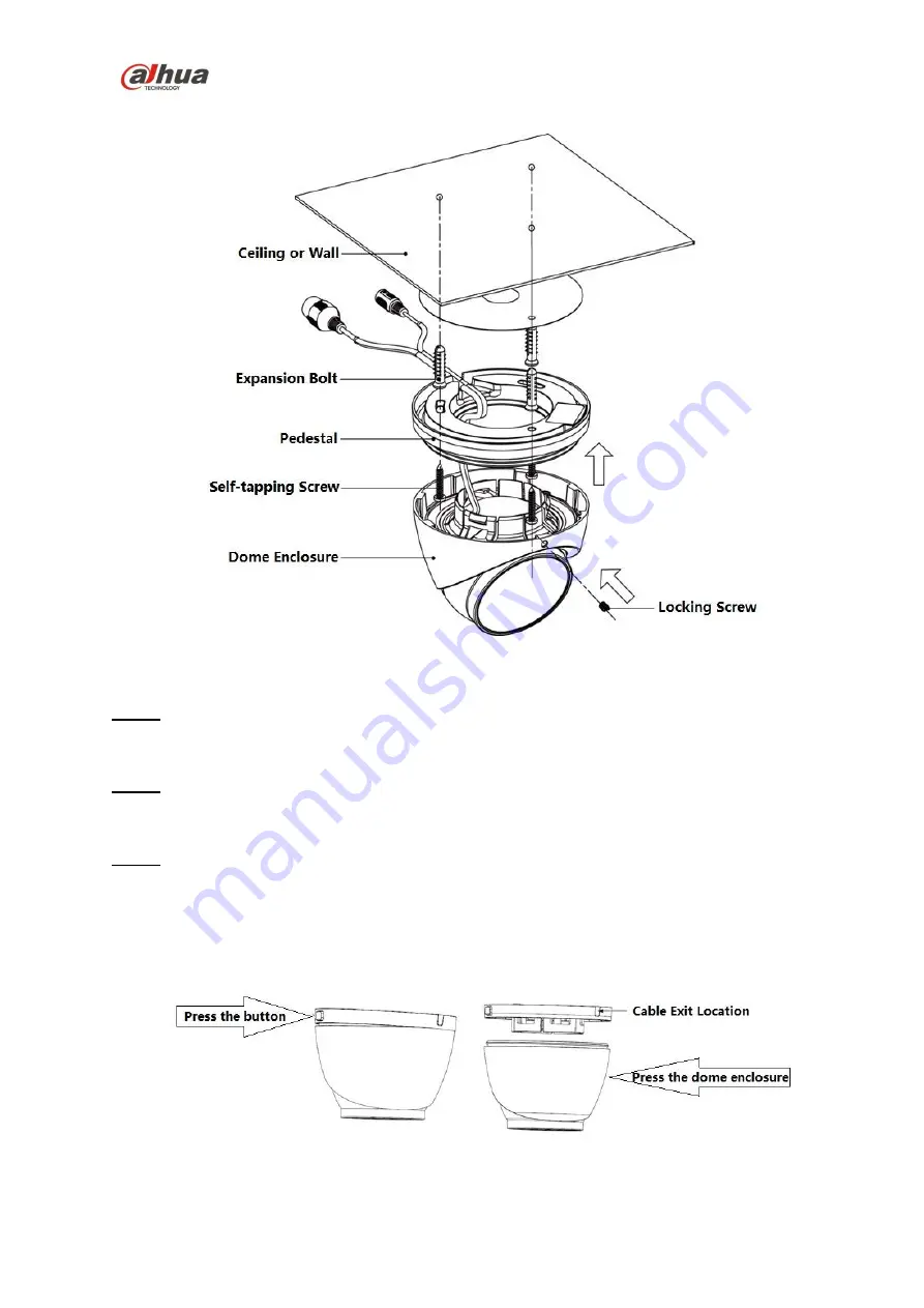
Figure 2-2 (b) 

Step 1 

Please take out the installation position map in the accessories bag, and then stick it on the ceiling or 

the wall. 

Step 2 

Dig bottom holes according to the installation position map and then insert three expansion bolts into 

the bottom holes. Secure these three bolts firmly.  

Step 3 

Disassemble the device 


For the device shown in Figure2-1 (a), the steps of disassembling the device are as follows:  

Step 1 Press the button on the pedestal to make it expand. 

Step 2 Press the dome enclosure down the cable exit to separate the pedestal and the dome 

enclosure and disassemble the device.  


Figure 2-3  


For the device shown in Figure 2-2 (b), loosen the locking screw, pull the enclosure downward, 

and then disassemble the device.                                                                                                                                                                                                                                                                                                                                                                                                          

Summary of Contents for N84CG52

Page 1: ...Dahua HD IR Network Dome Camera Quick Start Guide Dahua HD IR Network Dome Camera Quick Start Guide Version 1 0 0 Dahua Technology USA Ltd...

Page 2: ...vice at the same time it may result in device damage We assume no liability or responsibility for all the fires or electrical shock caused by improper handling or installation We are not liable for an...

Page 3: ...e of the device Dome cover is an optical device please don t touch or wipe cover surface directly during installation and use please refer to the following methods to deal with once dirt is found Stai...

Page 4: ...gainst harmful interference This equipment generates uses and can radiate radio frequency energy and if not installed and used in accordance with the instruction manual may cause harmful interference...

Page 5: ...Start Guide iv Table of Contents 1 Device Structure 1 1 1 Structure Components 1 1 2 Framework and Dimension 2 2 Device Installation 3 2 1 Installation Steps 3 3 Network Configuration 7 3 1 Modify IP...

Page 6: ...l product You can refer to the following figures for multiple function combination cable information See Figure 1 and Figure 1 2 Figure 1 1 Figure 1 2 Please refer to the following sheet for detailed...

Page 7: ...Description 4 DC 12V 12V DC power Connect DC 12V power input power Sheet 1 2 1 2 Framework and Dimension The following figures are for reference only which are used to know the device dimension please...

Page 8: ...allation Steps Note The installation figures are for reference only please refer to figure 2 1 a or 2 2 b according to the actual product Before the installation please make sure the installation envi...

Page 9: ...into the bottom holes Secure these three bolts firmly Step 3 Disassemble the device For the device shown in Figure2 1 a the steps of disassembling the device are as follows Step 1 Press the button on...

Page 10: ...ly Side wiring select to lead out the cable through side exit and add metal conduit and etc which can prevent the cable from being destroyed Figure 2 4 Figure 2 5 Step 5 Adjust pedestal position aim a...

Page 11: ...crystal head through main body of waterproof connector fixing rubber ring and waterproof locking cover make the crystal head of network cable and then insert it into the network cable 3 Put the main...

Page 12: ...difying IP address via Quick Configuration Tool also you can modify the IP address in the network parameters of the WEB interface please refer to the document in the disk WEB Operation Manual for more...

Page 13: ...Dahua HD IR Network Dome Camera Quick Start Guide 8 Figure 3 1 Step 4 Modify the camera IP address on the Net interface click Save to finish modification See Figure 3 2 for more details Figure 3 2...

Page 14: ...press Enter button and the system will pop out login dialogue box which is shown in Figure 3 3 Step 2 Please input your user name and password click Login and then the system will pop out WEB interfa...

Page 15: ...written notice All trademarks and registered trademarks mentioned are the properties of their respective owners If there is any uncertainty or controversy please refer to the final explanation of us P...

Reviews: